Introduction
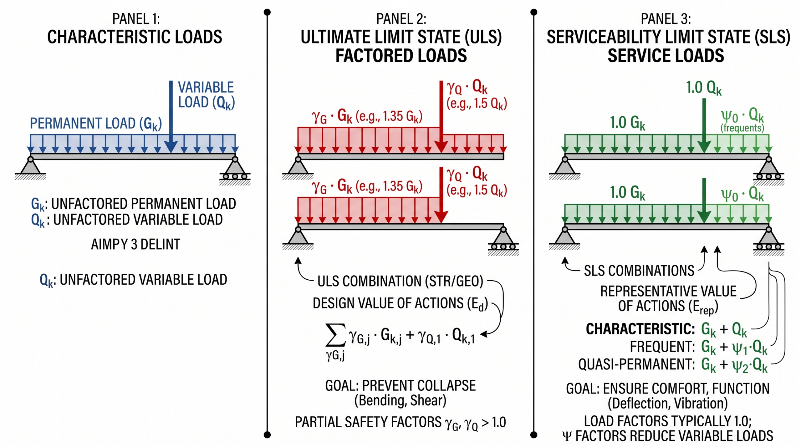
A structural model may contain dead load, live load, wind load, snow load, and many other actions.
However, engineers normally do not design a beam or column using these characteristic loads separately.
Therefore, these actions must be combined according to the relevant design situation.
This is where Eurocode load combinations become important.
At first, expressions containing symbols such as γG, γQ, ψ0, ψ1, and ψ2 can look complicated to junior engineers.
The basic idea, however, is simple:
Increase or reduce different actions according to their probability, importance, and the limit state being checked.
EN 1990 provides the basis for structural design, including principles for safety, serviceability, reliability, actions, and combinations of actions.
In this guide, we will focus on the practical difference between ULS and SLS load combinations and work through a simple example.
1. Start With the Different Types of Actions
Eurocode terminology commonly separates actions into several categories.
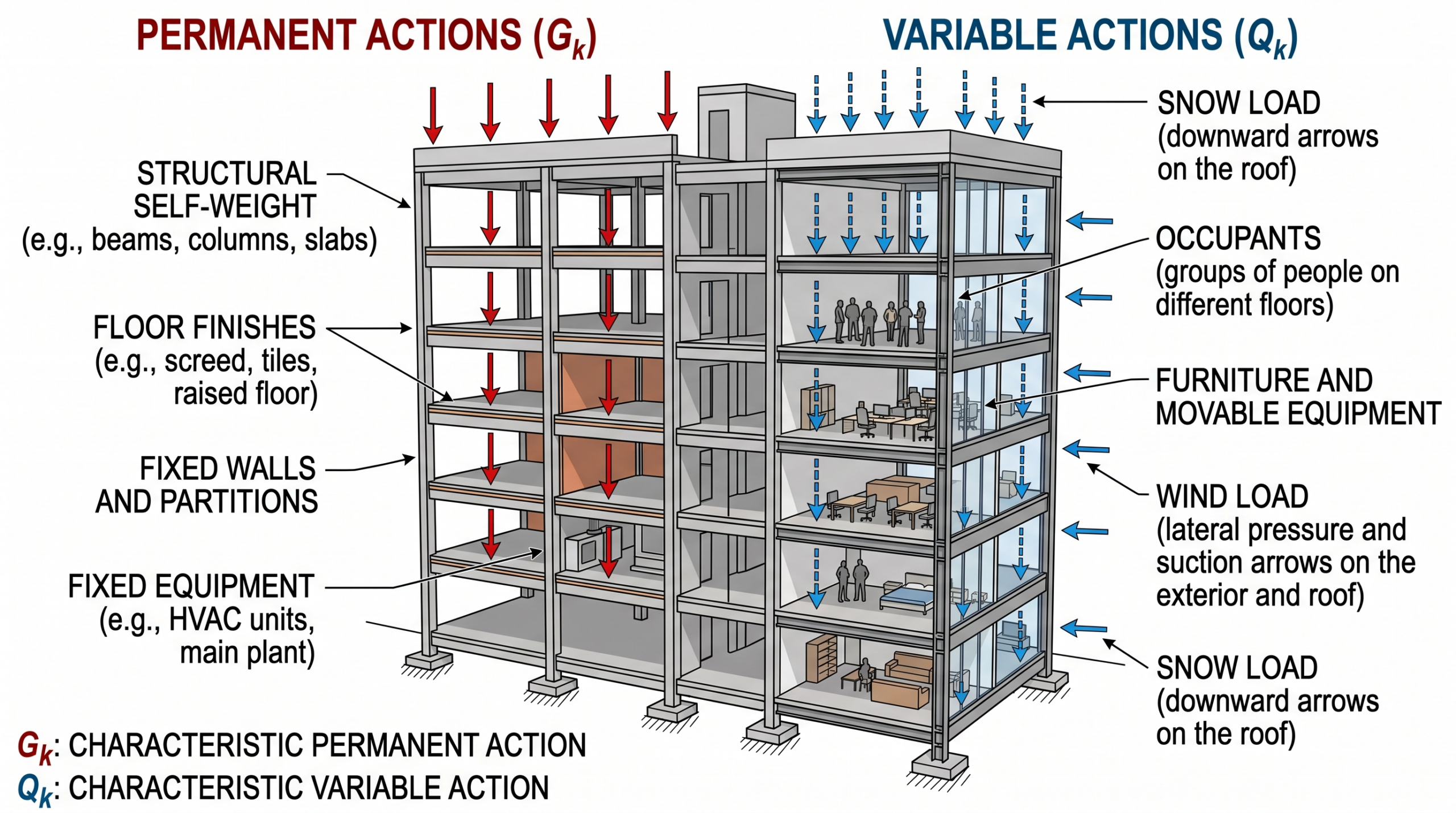
In practice, the two most important action categories for everyday building design are:
Permanent Actions — G
These remain relatively constant during the life of the structure.
Examples include:
- Self-weight of concrete or steel
- Floor finishes
- Permanent partitions
- Fixed equipment
- Cladding
The characteristic value is normally written as:
Gk
Variable Actions — Q
These can change during the life of the structure.
Examples include:
- Occupancy loads
- Furniture
- Storage loads
- Wind
- Snow
- Some imposed equipment loads
The characteristic value is normally written as:
Qk
In addition, Eurocode terminology distinguishes accidental and seismic actions where relevant.
2. What Is ULS?
ULS means Ultimate Limit State.
ULS checks whether a structure has sufficient safety against conditions such as:
- Excessive bending resistance demand
- Shear failure
- Compression failure
- Loss of stability
- Structural collapse
For example, in a simple building case with one unfavourable permanent action and one leading variable action, engineers frequently encounter the familiar form:
ULS = 1.35Gk + 1.50Qk
The recommended EN 1990 building values commonly associated with this form are:
γG = 1.35
for an unfavourable permanent action, and:
γQ = 1.50
for an unfavourable variable action.
These values are partial factors.
They convert characteristic actions into design actions.
What Do γG and γQ Mean?
The Greek letter γ (gamma) represents a partial factor.
Therefore:
γG
means the partial factor applied to a permanent action.
And:
γQ
means the partial factor applied to a variable action.
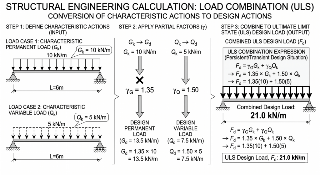
For example, if Gk = 10 kN/m, then:
1.35 × 10 = 13.5 kN/m
Similarly, if Qk = 5 kN/m, then:
1.50 × 5 = 7.5 kN/m
The combined ULS design load becomes:
13.5 + 7.5 = 21.0 kN/m
3. Why Do We Factor Loads at ULS?
Characteristic loads represent defined reference values for actions.
However, structural design must also account for uncertainty.
Actual loads may differ from assumed values, and structural behaviour cannot be predicted with perfect accuracy.
The partial-factor method provides a systematic way of introducing the required level of reliability into design.
As a result, the load used for a ULS resistance check can be greater than the characteristic service load.
A junior engineer should remember:
Characteristic load is not automatically the same as design load.
4. What Is SLS?
SLS means Serviceability Limit State.
SLS focuses on whether the structure performs properly during normal use.
Typical checks include:
- Deflection
- Crack width
- Vibration
- Stress limitations
- Appearance
- User comfort
A beam could theoretically have enough strength to avoid collapse but still deflect so much that it becomes unsuitable for use.
Therefore, both ULS and SLS must be considered.
5. ULS vs SLS: The Simple Difference
A useful way to remember the difference is:
ULS
Can the structure safely resist the design actions?
SLS
Will the structure remain usable and perform acceptably?
In other words, they answer different engineering questions.
For a simple beam:
ULS → strength
SLS → performance
This distinction is one of the most important concepts in limit-state structural design.
6. SLS Has More Than One Load Combination
Unlike ULS, however, SLS is commonly divided into several combinations.
EN 1990 distinguishes representative values of variable actions using ψ factors, including combination, frequent, and quasi-permanent values.
The three important SLS combinations are:
Characteristic Combination
Typically used when checking effects associated with relatively rare loading conditions.
Conceptually:
Gk + Qk,1 + Σψ0,i Qk,i
The leading variable action is taken at its characteristic value.
Accompanying variable actions are reduced using ψ0.
Meanwhile, the frequent combination represents conditions that occur more regularly.
Frequent Combination
Conceptually:
Gk + ψ1,1 Qk,1 + Σψ2,i Qk,i
The leading variable action is reduced using ψ1.
Other variable actions are normally represented using ψ2.
Finally, the quasi-permanent combination represents loading sustained for a significant part of the structure’s life.
Quasi-Permanent Combination
Conceptually:
Gk + Σψ2,i Qk,i
This represents loading that may be sustained for a significant part of the structure’s life.
It is particularly important when considering long-term structural effects.
7. What Are ψ0, ψ1 and ψ2?
The ψ factors reduce variable actions depending on how likely those actions are to occur simultaneously and for how long.
A simple way to understand them is:
ψ0 → combination value
ψ1 → frequent value
ψ2 → quasi-permanent value
For example, the JRC Eurocode worked material lists the following values for office imposed loads:
ψ0 = 0.7
ψ1 = 0.5
ψ2 = 0.3
while values differ for other action categories such as storage, congregation areas, roofs, and wind.
Therefore, engineers should never assume that one ψ factor applies to every type of variable action.
8. Simple Eurocode Load Combination Example
Consider a simply supported floor beam.
Assume:
Permanent load Gk = 10 kN/m
Office imposed load Qk = 5 kN/m
We will calculate several useful design combinations.
ULS Combination
Using:
1.35Gk + 1.50Qk
we obtain:
1.35 × 10 + 1.50 × 5
=
13.5 + 7.5
=
21.0 kN/m
This is the factored load used for the simplified ULS example.
SLS Characteristic Combination
With only one variable action:
Gk + Qk
=
10 + 5
=
15.0 kN/m
SLS Frequent Combination
For this example, using:
ψ1 = 0.5
we obtain:
Gk + ψ1Qk
=
10 + 0.5 × 5
=
12.5 kN/m
SLS Quasi-Permanent Combination
Using:
ψ2 = 0.3
we obtain:
Gk + ψ2Qk
=
10 + 0.3 × 5
=
11.5 kN/m
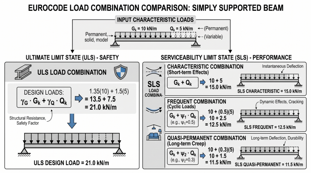
The image should visually compare:
Characteristic loads
Gk = 10 kN/m
Qk = 5 kN/m
↓
ULS design load = 21.0 kN/m
Characteristic SLS load = 15.0 kN/m
Frequent SLS load = 12.5 kN/m
Quasi-permanent SLS load = 11.5 kN/m
9. What Happens When There Are Several Variable Actions?
Real buildings rarely have only one variable action.
You may have:
- Imposed floor load
- Wind
- Snow
- Temperature
at the same time.
Eurocode combinations therefore distinguish between a leading variable action and accompanying variable actions.
The leading action receives the treatment appropriate to the selected combination.
Other variable actions are normally reduced using the relevant ψ factor.
A simplified ULS expression can be represented as:
ΣγG Gk + γQ,1 Qk,1 + ΣγQ,i ψ0,i Qk,i
The key idea is:
Not every variable action is assumed to reach its full characteristic maximum at exactly the same time.
10. Leading Variable Action: A Common Junior Engineer Mistake
Suppose a structure is affected by:
Live Load + Wind Load
You should not automatically assume that the same load is always the leading action.
One combination may consider:
Live load as leading
while another considers:
Wind as leading
Afterward, the structural effects are compared to determine which combination governs.
The governing combination depends on the member and the response being checked.
For example, wind may govern one column or frame while gravity loading governs another beam.
11. ULS and SLS Are Not One Single Combination
However, another common mistake is assuming that one ULS calculation covers every design situation.
“I have calculated 1.35G + 1.5Q, so my load combinations are finished.”
Not necessarily.
A real Eurocode project can require several combinations depending on:
- Design situation
- Type of action
- Leading variable action
- Favourable or unfavourable action
- ULS verification type
- SLS criterion
- National Annex
- Project requirements
EN 1990 also allows nationally determined choices for some combination rules and partial factors.
Therefore, the familiar 1.35G + 1.5Q expression is an excellent teaching example, but it should not be treated as a universal replacement for the complete code provisions.
12. Important: Check the National Annex
This point is especially important in real design work.
Eurocode includes Nationally Determined Parameters.
The applicable National Annex may specify or modify values and choices used for design in a particular country.
For example, EN 1990 allows National Annex choices relating to load-combination expressions and partial factors.
Therefore:
Do not copy load factors from another project or country without checking the applicable Eurocode, National Annex, and project design basis.
Also note that the second-generation Eurocodes are being introduced, with EN 1990:2023 forming part of that evolution, so the exact standard edition required for a project should always be confirmed.
13. Common Eurocode Load Combination Mistakes
Mistake 1 — Using Characteristic Loads Directly for ULS
Always distinguish between:
Characteristic action
and:
Design action
Mistake 2 — Applying 1.5 to Every Variable Action Without ψ Factors
When several variable actions occur, accompanying actions may require combination factors.
Mistake 3 — Forgetting the Leading Variable Action
Wind, imposed load, and snow may each need to be considered as the leading action in different combinations.
Mistake 4 — Using ULS Loads for Every SLS Check
ULS and SLS serve different purposes.
Do not use a strength combination automatically for a serviceability check.
Mistake 5 — Ignoring the National Annex
This can result in the wrong partial factors, ψ values, or combination rules being used.
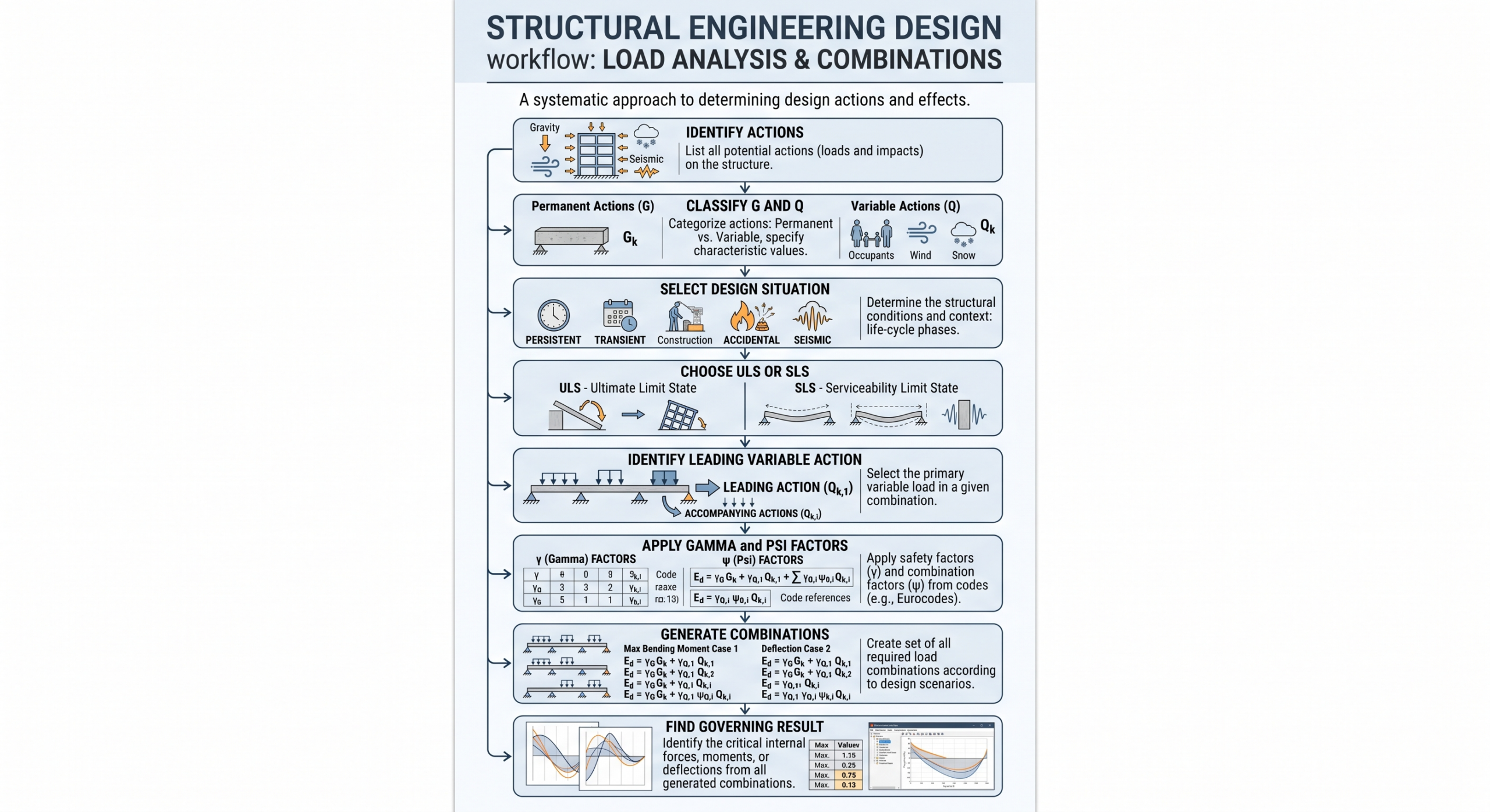
14. A Quick Workflow for Junior Structural Engineers
First, use the following sequence when preparing Eurocode load combinations:
Step 1
Identify all actions.
G, Q, Wind, Snow, Temperature, etc.
↓
Step 2
Classify each action as permanent, variable, accidental, or seismic where applicable.
↓
Step 3
Determine the required design situation.
↓
Step 4
Select the relevant ULS or SLS combination.
↓
Step 5
Identify the leading variable action.
↓
Step 6
Apply the appropriate γ and ψ factors.
↓
Step 7
Repeat combinations where another variable action could govern.
↓
Step 8
Compare the structural effects and identify the governing case.
15. Practical Engineering Tip
Before relying on structural analysis software, calculate one or two combinations manually as a quick verification.
For example, if your software reports:
ULS = 21 kN/m
for:
Gk = 10 kN/m
and:
Qk = 5 kN/m
you can quickly check:
1.35 × 10 + 1.50 × 5 = 21 kN/m
However, if the software result is completely different, investigate why.
Possible reasons include:
- Self-weight added automatically
- Different load factors
- Multiple variable actions
- ψ factors
- National Annex settings
- Incorrect load-case assignments
A simple hand calculation is one of the fastest ways to identify modeling errors.
Final Thoughts
Eurocode load combinations become much easier once you stop seeing them as a collection of Greek symbols.
Start with four questions:
What is the permanent action?
What is the variable action?
Am I checking ULS or SLS?
Which variable action is leading?
Then the purpose of γG, γQ, ψ0, ψ1, and ψ2 becomes much clearer.
More importantly, understanding the logic behind the combination is more valuable for junior structural engineers than simply memorizing equations.
1.35G + 1.5Q
The equation is easy.
Understanding why and when to use it is the real engineering skill.
Related Articles
- Structural Load Paths Explained: How Loads Travel Through a Building
- Gravity Load Path in Buildings: A Step-by-Step Guide for Junior Structural Engineers
- Partial Safety Factors in Structural Design: A Practical Guide
- ASCE 7-22 Wind Loads Explained: A Practical Guide for Junior Structural Engineers