Introduction
Every load applied to a building needs a continuous path to the ground.
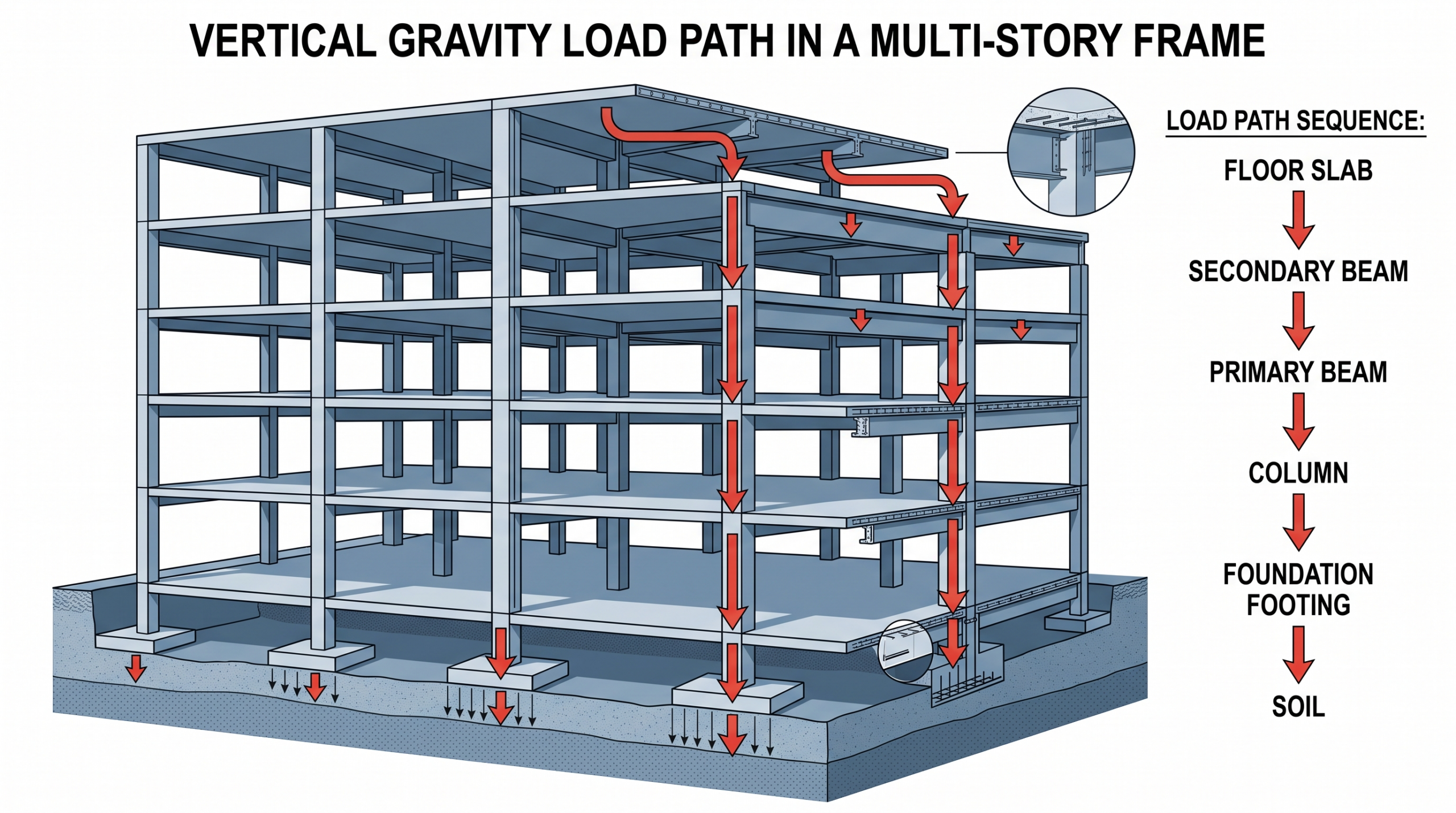
A floor load may begin at a slab, move into beams, continue through columns, and finally reach the foundation and supporting soil.
This sequence is called the gravity load path.
Understanding the gravity load path is one of the most important skills for junior structural engineers because it helps you understand not only calculations, but also how an entire structural system behaves.
In this guide, we will follow a simple building load from the floor all the way to the foundation.
What Is a Gravity Load Path?
A gravity load path is the route vertical loads follow through a structure until they reach the ground.
Typical gravity loads include:
- Structural self-weight
- Floor finishes
- Walls and partitions
- Mechanical and electrical equipment
- Furniture
- Occupants
- Storage loads
- Roof loads
A typical reinforced concrete or steel building may have the following load path:
Floor Load → Slab → Beam → Girder → Column → Foundation → Soil
Every connection between these components must safely transfer the forces to the next structural element.
A structural member is only as reliable as the load path connected to it.
Why the Gravity Load Path Matters in Structural Design
Structural calculations are often performed member by member.
You may design a slab first, then calculate a beam, and later check a column.
However, these members do not work independently.
The reaction from one member often becomes the load on another.
For example:
Slab load
↓
becomes a beam load
↓
the beam reaction becomes a column load
↓
the column load becomes a foundation load
Understanding this relationship helps engineers detect missing loads and incorrect assumptions before they become serious design problems.
Step 1: Gravity Loads Start at the Floor
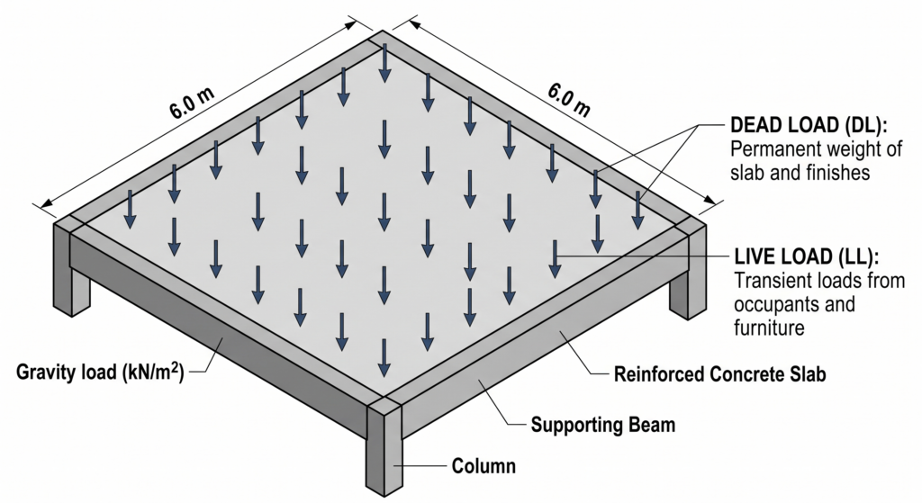
Consider a simple floor panel measuring:
6 m × 6 m
Assume the floor carries:
- Dead load = 4 kN/m²
- Live load = 3 kN/m²
For this simplified example:
Total service gravity load = 7 kN/m²
The floor area is:
6 × 6 = 36 m²
Therefore, the total load acting on the panel is:
7 × 36 = 252 kN
This load must now move from the slab into the supporting structural members.
Step 2: The Slab Transfers Load to the Beams
The direction of load transfer depends on how the slab spans.
For a simple one-way slab, the floor load transfers mainly to two opposite supporting beams.
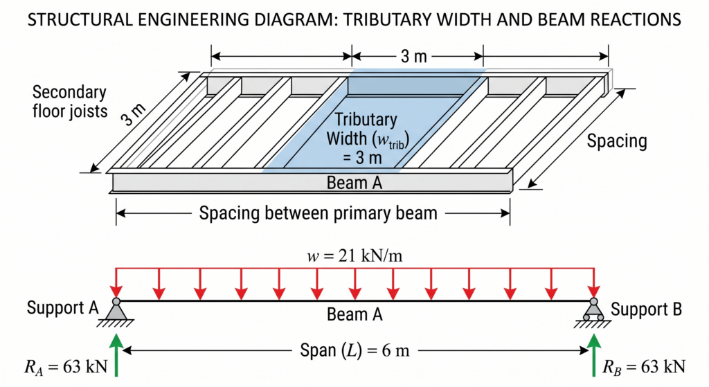
Engineers normally use the tributary area or tributary width to determine how much load each beam receives.
For our simplified example, assume each beam supports a tributary width of:
3 m
The distributed line load on one beam becomes:
7 kN/m² × 3 m = 21 kN/m
So each supporting beam receives approximately:
21 kN/m
over its 6 m span.
This conversion from an area load to a line load is a fundamental part of understanding the gravity load path.
Step 3: Beams Transfer Gravity Loads to Columns
Now consider one simply supported beam:
- Beam span = 6 m
- Uniform load = 21 kN/m
The total load on the beam is:
21 × 6 = 126 kN
For a symmetrical simply supported beam, each support carries half of the total load.
Therefore:
Reaction at each end = 126 / 2 = 63 kN
The slab load has now traveled through the beam and reached the columns.
Step 4: Columns Collect Loads from Multiple Floors
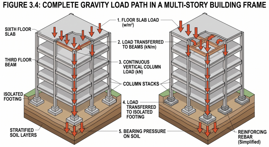
Columns are different from individual beams because their loads usually accumulate as they move downward through the building.
A column on an upper floor may support only one or two levels.
A column near the bottom of a ten-story building may support loads from many floors above it.
Conceptually:
Roof load
↓
10th-floor load
↓
9th-floor load
↓
8th-floor load
↓
…
↓
Ground-floor column
This is why lower-level columns often carry much larger axial forces than upper-level columns.
When reviewing a structural model, column forces should normally show a logical increase toward the lower floors.
A sudden decrease may indicate a modeling or load-transfer problem.
Step 5: Columns Transfer the Load to the Foundation
At the bottom of the structure, the column transfers its axial load to a foundation.
Depending on the building and ground conditions, the foundation could be:
- Isolated footing
- Combined footing
- Strip footing
- Raft foundation
- Pile cap
- Pile foundation
The purpose of the foundation is to distribute structural forces into the supporting ground safely.
The gravity load path therefore continues:
Column → Foundation → Soil
The path is complete only when the load reaches the ground.
Gravity Load Path and Tributary Area
The concept of tributary area is essential when calculating gravity loads.
A structural member generally receives loads from the portion of the floor that is considered to belong to that member.
For example, an interior column may receive loads from surrounding floor panels.
The tributary area can often be estimated by drawing boundaries halfway between adjacent columns.
If an interior column has a tributary area of:
6 m × 6 m = 36 m²
and the floor load is:
7 kN/m²
the approximate floor load delivered to the column would be:
36 × 7 = 252 kN per floor
before considering additional factors such as beam self-weight, column self-weight, load combinations, or system-specific behavior.
Tributary areas provide a quick way to check whether computer-analysis results are reasonable.
Gravity Load Path vs Lateral Load Path
Junior engineers should distinguish between gravity and lateral load paths.
Gravity Load Path
Primarily transfers vertical loads such as:
- Dead loads
- Live loads
- Equipment loads
Typical path:
Slab → Beam → Column → Foundation
Lateral Load Path
Transfers horizontal forces such as:
- Wind
- Earthquake forces
A typical path may be:
Cladding/Floor → Diaphragm → Frame or Shear Wall → Foundation
A building needs a complete and reliable path for both types of loading.
Common Gravity Load Path Mistakes
1. Missing Beam Reactions
A beam reaction must become a load on its supporting element.
If the reaction disappears between structural members, the load path is incomplete.
2. Ignoring Transfer Structures
Transfer girders, transfer slabs, and discontinuous columns can significantly change how loads move through a building.
These areas require special attention.
3. Incorrect Tributary Areas
A small error in tributary width can create large errors when repeated across several floors.
Always check the actual framing geometry.
4. Forgetting Self-Weight
Structural elements also create gravity loads.
Beams, columns, slabs, walls, and foundations all contribute their own weight.
5. Trusting Software Without a Hand Check
Structural analysis software can calculate forces accurately only when the model is correct.
A simple tributary-area calculation can often reveal unrealistic model results immediately.
A Simple Gravity Load Path Check for Junior Engineers
When reviewing a structure, ask these questions:
- Where does the load begin?
- Which member receives it first?
- Where does that member transfer its reaction?
- Does the next member include that force?
- Do column loads increase logically toward the lower floors?
- How does the final column load reach the foundation?
- Can the foundation safely transfer that load to the ground?
If you cannot clearly trace the load from its source to the ground, the structural system deserves another review.
Practical Engineering Tip
Before opening structural analysis software, sketch the expected load path by hand.
For a typical floor, draw:
Slab
↓
Secondary Beam
↓
Primary Beam
↓
Column
↓
Foundation
Then estimate the loads using tributary areas.
After running the structural model, compare the software reactions with your hand estimate.
They do not need to match perfectly, but they should be reasonably close and physically logical.
This simple habit can catch many modeling mistakes.
Gravity Load Path Example Summary
Our simplified example started with:
Floor load = 7 kN/m²
For a 6 m × 6 m panel:
Total panel load = 252 kN
The slab transferred the load to beams.
Each beam received approximately:
21 kN/m
A 6 m beam therefore carried:
126 kN
and produced approximately:
63 kN reaction at each support
That reaction then continued through the columns and foundation until it reached the soil.
This is the basic idea behind every gravity load path.
Final Thoughts
Understanding the gravity load path in buildings is more important than memorizing individual structural equations.
When you understand where loads originate, how they move between structural members, and where they finally reach the ground, structural calculations become much easier to interpret.
For junior structural engineers, load-path thinking is also one of the best ways to identify modeling errors and develop good structural intuition.
Before checking whether a member is strong enough, always ask one question:
Where did this load come from, and where will it go next?
Related Articles
- Structural Load Paths Explained: How Loads Travel Through a Building
- Partial Safety Factors in Structural Design
- ASCE 7-22 Wind Loads Explained: A Practical Guide for Junior Structural Engineers
- Eurocode Load Combinations Explained (upcoming article)