Introduction
This hands‑on tutorial walks a beginner or junior engineer through modeling a single‑bay, single‑span steel portal frame in STAAD.Pro. The goal is to show the modelling logic, required inputs and unit checks, how to use STAAD.Pro’s built‑in wind and seismic load generators (ASCE), how to run a linear analysis, what outputs to inspect, simple verification checks, and a troubleshooting checklist of common errors.
Deliverables you will produce by following this tutorial: a working STAAD model file, a short set of output checks (reactions, mode shapes, displacements, member forces) and a short report checklist for review.
Educational disclaimer
This article is for educational purposes only. It explains workflow steps and checks; it does not replace professional judgement, official code documents, or software manuals. Always verify model inputs and outputs against project requirements and the STAAD.Pro documentation.
Key Takeaways
- Plan geometry, connections, and simplifications before starting the model.
- Choose and verify units early. Unit errors are a common source of mistakes.
- Use STAAD.Pro’s wind and seismic generators (ASCE) but inspect the generated pressure and lateral tables in the input file.
- Always perform quick hand or spreadsheet checks to verify total weight, base shear plausibility, and a sample member force.
- Document assumptions, units, and critical output screenshots for review.
1. Project setup and modelling logic (before opening STAAD.Pro)
Start on paper. Sketch the portal frame showing column and beam locations, the single bay width, and the span length. Decide these modelling points:
- 2D plane frame vs 3D model. For a single portal frame with no out‑of‑plane effects, a 2D plane frame is usually sufficient.
- Connections: assume rigid connections at beam‑column junctions for a true portal action, or pinned ends where rotation is allowed. Write this assumption down; it changes moment distribution significantly.
- Mass estimate: prepare a simple mass estimate (roof and beam weights) to use later when checking seismic load generation.
2. STAAD.Pro model creation: step‑by‑step
Units selection
Choose your units first in STAAD.Pro. Units affect loads, geometry and results. Check length, force and mass units. Mistakes here lead to large errors later.
Create nodes and members
Use coordinate input or snapping to place nodes for columns and beams. Draw members between nodes to form the frame. Keep node numbering and an explanatory drawing so reviewers understand connectivity.
Assign material and sections
Assign a steel material (common library options exist in STAAD.Pro). Pick standard steel profiles for columns and beams from the section library. If you create a custom section, enter the section properties carefully.
Define member releases
Where rotations or axial continuity are not present, apply member end releases (for example, a pinned beam‑column end). A release removes certain internal force components — document why you applied each release.
3. Supports and boundary conditions — input checks
Assign supports at base nodes. Typical support types are fixed (no translation or rotation) or pinned (no translation but rotations allowed). Check these items:
- Support type matches assumed foundation behaviour.
- There are no duplicate or contradictory supports at a node.
- Quick check: run a modal analysis; large rigid‑body motions mean insufficient restraints.
4. Loads: dead, live and non‑structural
Define dead loads including self‑weight. STAAD.Pro can automatically include member self‑weight — verify the units and the direction.
Define live loads as separate basic load cases (do not apply load factors here). For area loads (roof), apply area or panel loads so STAAD.Pro converts them to element loads correctly. Keep a simple spreadsheet showing how you converted areas to line loads for traceability.
5. Generating code‑based wind loads in STAAD.Pro (ASCE workflow)
STAAD.Pro includes automatic wind load generation. ASCE requires parameters such as basic wind speed, exposure category, and importance factor. Gather these from project data or code guidance.
In STAAD.Pro, open the Wind Definitions (or wind loading) page, enter the ASCE parameters and the wind direction(s). Run the generator. The software creates pressure vs height tables and attaches loads to members or panels.
Input checks after generation:
- Inspect the generated pressure vs height table in the input or output file.
- Verify wind direction and ensure loads are applied to the intended faces or members.
- Confirm sign convention — wind pressure should push in the correct global direction.
6. Generating seismic loads (ELF) in STAAD.Pro
Decide if Equivalent Lateral Force (ELF) is appropriate. ELF is commonly used for regular, low‑rise frames. Enter ASCE seismic parameters (site seismicity, seismic design category and response coefficients) in STAAD.Pro’s seismic definition page and generate the lateral loads.
Key input checks:
- Ensure mass source is correct: include dead weight and appropriate portion of live load if required by code.
- Verify that STAAD.Pro attached lateral loads to the correct nodes and levels.
- If using modal methods later, check modal mass participation to ensure adequate mass is captured by the first few modes.
7. Load combinations and analysis setup
Create load combinations separately. Do not put load factors into basic load cases. Use the project or code required combinations (service and strength/combo sets). For a linear check on a single frame, linear static analysis is often appropriate; for seismic you may choose ELF or modal response depending on regularity.
Before running, inspect solver settings and default tolerances. For beginners, the default solver is usually fine — but read warnings after the run.
8. Running the model and initial plausibility checks
Run the analysis. First check the STAAD.Pro messages for errors and warnings. Common issues appear as warnings about singular stiffness or unsupported nodes.
Quick plausibility checks:
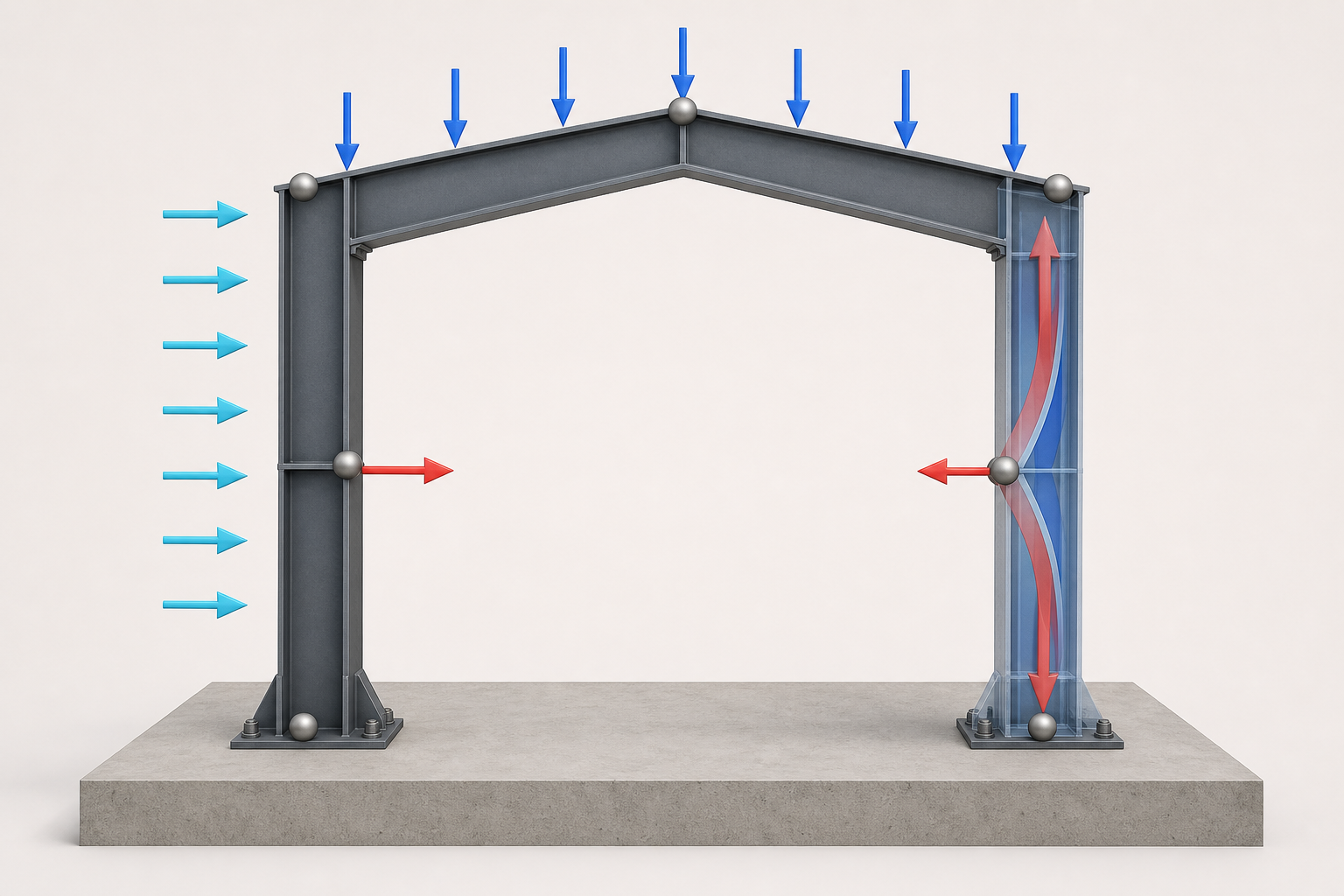
- Mode shapes: ensure the first few modes show expected frame sway or global bending — not large rigid‑body translation that suggests missing restraints.
- Total reactions: the sum of vertical reactions should equal applied gravity loads (dead + applied live loads where appropriate).
- Gross displacements: check direction and relative magnitude; very large displacements indicate a modelling or support error.
9. Detailed output checks
Inspect these outputs and why they matter:
- Support reactions and base shear — compare STAAD results with your simple hand estimate of total weight and approximate lateral demand.
- Member forces and diagrams — view bending moment, shear and axial force diagrams at critical members and nodes.
- Deflections and drift — check against expected limits and verify deformed shape is reasonable.
- Utilization ratios — if you use built‑in design checks, read ‘OK’ and ‘FAIL’ carefully and trace failed members back to loads and boundary conditions.
10. Verification and simple hand checks
Simple checks catch common errors:
- Sum vertical loads that you applied (self‑weight + roof and beam loads) and compare with the sum of vertical reactions in STAAD.Pro.
- Compare a simple estimate of lateral demand (based on your mass estimate and expected seismic level) with the model base shear to ensure order‑of‑magnitude agreement.
- Pick one critical beam, calculate an approximate bending demand by hand or in a spreadsheet using the load you applied to that span and compare to STAAD’s bending diagram.
These checks do not replace full design calculations but help detect missing self‑weight, wrong load application areas, or unit mistakes.
11. Common beginner mistakes and how to fix them
- Unit errors — verify units for geometry, loads and material properties. Fix by reselecting the correct units and rechecking load values.
- Incorrect supports — missing supports cause rigid body motion; over‑constraining creates false stiffness. Check by running a modal analysis and looking for rigid modes or excessive restraint forces.
- Wrong wind panel grouping — generated wind pressures may not attach to intended panels. Inspect the generated pressure table and the load application list in the input file.
- Applying load factors in basic cases — load factors belong in combinations. Keep basic cases unfactored, then build combinations per code requirements.
12. Producing a short QA report and export checklist
A concise QA report should include:
- Model assumptions and chosen units.
- Material and section table.
- List of primary load cases generated (dead, live, wind, seismic) and key screenshots: mode shape, maximum deflection, bending moment diagram of a critical member.
- Summary table of checks (reaction balance, mass check, sample bending check) and any unresolved warnings.
Export STAAD output tables and relevant DXF or screenshots for reviewers.
Conclusion
Modeling a single‑bay portal frame in STAAD.Pro and using the built‑in ASCE wind and seismic load generators is a practical way for beginners to learn software workflow and code application. The critical practices are planning before modeling, verifying units and supports, inspecting generated code loads, running plausibility checks, and documenting assumptions and results. Simple hand checks and a short QA report improve confidence and make reviews faster.
Sources
- Bentley — STAAD product page
- Bentley Knowledgebase — How to apply wind load in STAAD.Pro
- STAAD.Pro Technical Reference / User Manual
- ASCE — ASCE 7 standard overview (Minimum Design Loads)
- Practical guidance for beginners / common mistakes
Appendix: Quick pre‑analysis checklist
- Units set and verified.
- Geometry and member connectivity reviewed.
- Material and sections assigned.
- Supports checked and not over‑constrained.
- Self‑weight enabled and area loads converted and documented.
- Wind and seismic parameters entered; generated tables inspected.
- Load combinations created; basic cases unfactored.
- Run and review warnings; perform balance and plausibility checks.