
Introduction: ACI 318 vs Eurocode 2
ACI 318 vs Eurocode 2 is one of the most useful comparisons for structural engineers working across international projects. Engineers worldwide use both standards for reinforced concrete design, but each standard organizes safety concepts, material factors, stress blocks, and calculation procedures differently.
When engineers design the same reinforced concrete beam using both standards, they may obtain different formulas and reinforcement requirements. This article explains the underlying design philosophies, compares the major calculation concepts, and walks through a simplified beam reinforcement example.
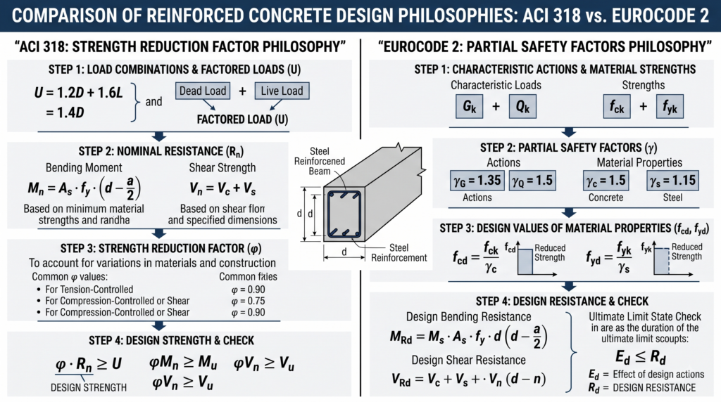
Suggested alt text: ACI 318 vs Eurocode 2 structural concrete design comparison
Why This Comparison Matters in Practice
For structural engineering consultants and global contractors, selecting or complying with a specific design standard is not simply an academic exercise. The selected code can influence member dimensions, reinforcement quantities, material procurement, detailing, and construction procedures.
Even relatively small changes in reinforcement quantity can affect project cost and embodied carbon. For this reason, engineers working internationally should understand not only the formulas in each code, but also the safety philosophy behind them.
Comparing the Design Philosophies of ACI 318 and Eurocode 2
How the Strength Reduction Factor Works in ACI 318
In the ACI 318 approach, engineers use factored loads together with a strength reduction factor, commonly denoted by φ. First, they calculate the nominal resistance of the member and then apply the appropriate φ factor to obtain the design strength.
We can express the basic design requirement conceptually as:
φRn ≥ U
- φ = strength reduction factor
- Rn = nominal resistance or nominal strength
- U = factored load effect
A simple way to think about this approach is: calculate the nominal member strength and then apply a reduction factor to obtain the usable design resistance.
Eurocode 2: Partial Material Factor Approach
By contrast, Eurocode 2 uses factored actions and converts characteristic material strengths into design strengths using separate partial safety factors.
For concrete:
fcd = fck / γc
For reinforcing steel:
fyd = fyk / γs
- fcd = design compressive strength of concrete
- fck = characteristic compressive cylinder strength
- γc = partial safety factor for concrete
- fyd = design yield strength of reinforcement
- fyk = characteristic yield strength of reinforcement
- γs = partial safety factor for reinforcing steel
The key idea is that Eurocode reduces the relevant material strengths before calculating the design resistance.
Conceptual Comparison
| Design Approach | Conceptual Workflow |
|---|---|
| ACI 318 | Factored Loads → Nominal Resistance Rn → Apply φ → Design Resistance |
| Eurocode 2 | Characteristic Material Strength → Apply γ Factors → Design Material Strength → Design Resistance |
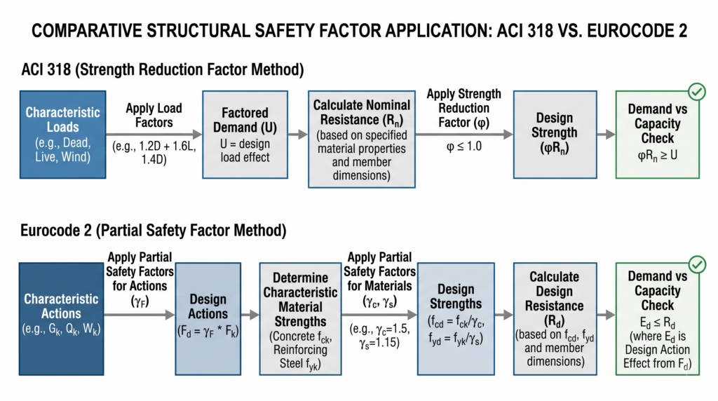
Suggested alt text: ACI 318 and Eurocode 2 safety factor workflow
Concrete Compression Stress Blocks
When bending acts on a reinforced concrete beam, a compression zone develops near one face while the longitudinal reinforcement generally resists tension on the opposite side.
The actual concrete compression stress distribution is nonlinear. For practical design calculations, both ACI 318 and Eurocode 2 use simplified equivalent stress-block models.
ACI 318: Whitney Stress Block
ACI 318 uses the well-known Whitney equivalent rectangular stress block. A simplified expression for the concrete compression force is:
C = 0.85 f’c b a
with:
a = β1 c
- f’c = specified concrete compressive strength
- b = beam width
- a = equivalent rectangular compression-block depth
- β1 = stress-block coefficient
- c = neutral-axis depth
Eurocode 2: Design Stress Block
Eurocode 2 also uses simplified concrete stress blocks for flexural design. Unlike the ACI approach, the concrete design strength is based on the characteristic material strength together with the applicable partial material factors and other code coefficients.
Engineers commonly represent the design compressive strength conceptually as:
fcd = fck / γc
Always obtain the exact design stress-block parameters from the applicable Eurocode provisions and, where relevant, the National Annex.
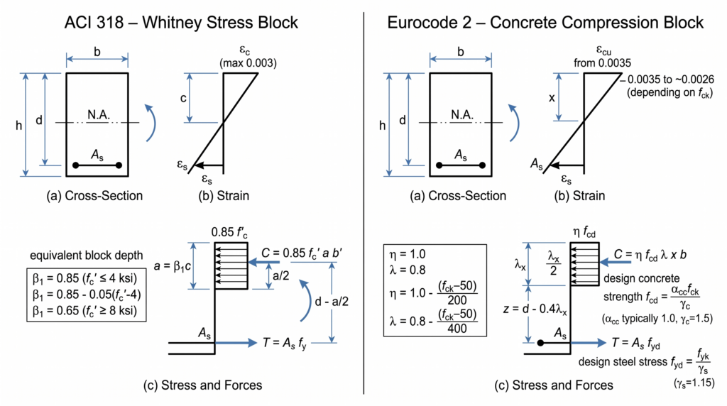
Suggested alt text: ACI Whitney stress block vs Eurocode 2 concrete stress block
Key Difference
| ACI 318 | Eurocode 2 |
|---|---|
| Uses nominal material strength in the resistance model and applies a strength reduction factor φ to the nominal resistance. | Uses design material strengths derived using partial safety factors before calculating the design resistance. |
| Uses the Whitney stress-block concept for concrete flexural compression. | Uses Eurocode-defined concrete stress-block parameters. |
| Reliability adjustment is expressed partly through φ. | Reliability adjustment is expressed partly through material partial factors such as γc and γs. |
Key Design and Engineering Considerations
Concrete Cylinder vs Cube Strength
ACI 318 typically specifies concrete compressive strength using standard cylinder strength, written as f’c.
Eurocode concrete classes identify both cylinder and cube strengths. For example, concrete class C30/37 represents approximately:
- fck = 30 MPa characteristic cylinder strength
- fck,cube = 37 MPa characteristic cube strength
Do not interchange these values without first confirming which strength definition the design equation requires.
Ductile Flexural Behavior
Both design systems include provisions that promote ductile flexural behavior rather than sudden brittle failure. Therefore, engineers should check the reinforcement ratio, neutral-axis depth, section strain state, and code-specific detailing limits instead of assuming that the tensile reinforcement automatically reaches the required strain condition.
Serviceability Limit States
Ultimate limit state checks address structural safety, while serviceability checks address the performance of the structure during normal use.
- Crack-width control
- Deflection limits
- Vibration
- Durability-related performance
- User comfort where applicable
Practical Case Study: Reinforced Concrete Beam
The following simplified example compares how ACI 318 and Eurocode 2 can approach the tensile reinforcement requirement for a rectangular singly reinforced concrete beam.
Design bending moment = 200 kN·m
Symbol Definitions
| Symbol | Definition |
|---|---|
| b | Beam width |
| d | Effective depth to tensile reinforcement |
| Mu | Factored design bending moment in the ACI example |
| MEd | Design bending moment in the Eurocode example |
| Mn | Nominal flexural resistance |
| f’c | Specified concrete cylinder compressive strength |
| fck | Characteristic concrete cylinder strength |
| fy | Specified reinforcement yield strength |
| fyk | Characteristic reinforcement yield strength |
| a | Equivalent rectangular compression-block depth |
| c | Neutral-axis depth |
| z | Internal lever arm |
| K | Normalized bending parameter used in the Eurocode example |
| φ | ACI strength reduction factor |
| As | Required tensile reinforcement area |
Given Design Parameters
| Parameter | Symbol | Value |
|---|---|---|
| Beam Width | b | 300 mm |
| Effective Depth | d | 500 mm |
| Design Bending Moment | Mu / MEd | 200 kN·m |
| Concrete Compressive Strength | f’c / fck | 30 MPa |
| Steel Yield Strength | fy / fyk | 400 MPa |
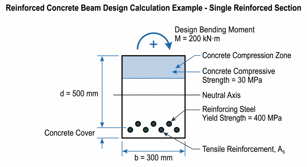
Show: b = 300 mm, d = 500 mm, As, compression zone, M = 200 kN·m, concrete = 30 MPa, steel = 400 MPa.
Suggested alt text: Reinforced concrete beam design example for ACI 318 vs Eurocode 2
ACI 318 Flexural Calculation
Core Equations
The flexural design requirement is:
Mu ≤ φMn
For a singly reinforced rectangular section:
Mn = As fy (d − a/2)
The equivalent compression-block depth is:
a = As fy / (0.85 f’c b)
Illustrative Calculation
Assuming the applicable flexural strength reduction factor is:
φ = 0.90
Substituting the example values into the flexural resistance relationship gives an illustrative required reinforcement area of approximately:
As ≈ 1,185 mm²
Engineers should still verify this value against the applicable minimum and maximum reinforcement, strain, detailing, development, and serviceability requirements.
Eurocode 2 Flexural Calculation
Core Equations
We can calculate a simplified normalized bending parameter as:
K = MEd / (b d² fck)
In this illustrative example, we estimate the internal lever arm using:
z = d [0.5 + √(0.25 − K/1.134)]
subject to the applicable lever-arm limit.
We then estimate the required tensile reinforcement from:
As = MEd / (fyd z)
where the steel design strength is based on:
fyd = fyk / γs
Illustrative Calculation
For the example parameters:
K = 200 × 10⁶ / (300 × 500² × 30) = 0.0889
The corresponding illustrative lever arm is approximately:
z ≈ 457 mm
Using the simplified steel design strength relationship gives an illustrative required reinforcement area of approximately:
As ≈ 1,257 mm²
Comparison of the Illustrative Results
| Design Code | Illustrative Required Reinforcement |
|---|---|
| ACI 318 | ≈ 1,185 mm² |
| Eurocode 2 | ≈ 1,257 mm² |
For this simplified example, the Eurocode-based calculation produces approximately 6% more tensile reinforcement than the ACI-based calculation.
However, do not interpret this result as a universal rule. Different load combinations, material grades, section dimensions, ductility requirements, National Annex values, detailing rules, and serviceability criteria can change the comparison significantly.
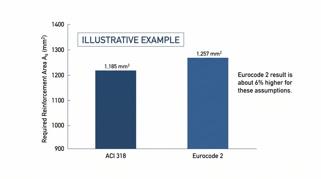
ACI 318 ≈ 1,185 mm² / Eurocode 2 ≈ 1,257 mm².
Suggested alt text: ACI 318 vs Eurocode 2 reinforcement comparison
Limitations of the Example
- Shear reinforcement design
- Anchorage and development length
- Minimum and maximum reinforcement requirements
- Crack-width verification
- Long-term deflection
- Other serviceability requirements
Note: This example is intended for educational comparison only and should not replace project-specific structural design or verification using the applicable code edition.
Common Mistakes Beginners Make
- Mixing cylinder and cube strengths: Always verify which concrete strength definition is required by the equation being used.
- Mixing safety-factor systems: Do not insert Eurocode design strengths into ACI resistance equations or vice versa without a clearly justified conversion.
- Ignoring section strain and ductility checks: Do not assume that a section automatically satisfies the required ductility conditions.
- Ignoring serviceability: A flexural strength calculation alone does not complete the design of a reinforced concrete member.
- Comparing reinforcement quantities without matching assumptions: Ensure that the same geometry, loading basis, material grades, and design scope are being compared.
Practical Recommendations for Engineers
- Confirm the exact code edition and project design basis before beginning calculations.
- Keep ACI and Eurocode calculations separate rather than mixing equations or safety factors.
- Document the source of all load, resistance, and material factors.
- Verify ductility, detailing, anchorage, shear, and serviceability requirements in addition to flexural strength.
- When comparing two code systems, use identical geometry and loading assumptions wherever possible.
Conclusion
ACI 318 vs Eurocode 2 is not simply a comparison of two different equations. The standards organize structural reliability, material resistance, load effects, and detailing requirements differently.
ACI 318 generally expresses resistance through nominal strength and an applicable strength reduction factor, while Eurocode 2 uses design material properties derived through partial safety factors. Understanding this distinction helps engineers interpret the equations correctly and avoid mixing incompatible design assumptions.
For engineers working internationally, the most important skill is not memorizing which code produces more reinforcement in one example. It is understanding the design philosophy well enough to apply each standard consistently and verify whether the final result makes engineering sense.
FAQ
Is ACI 318 or Eurocode 2 more economical?
There is no universal answer. Reinforcement quantities and member sizes depend on load combinations, geometry, material grades, detailing rules, serviceability requirements, National Annex provisions, and the governing limit state. A code that produces less reinforcement in one simplified flexural example may not do so for another structural system.
Why Do Eurocode Calculations Often Use 0.87fyk for Reinforcing Steel?
In simplified calculations, engineers obtain the steel design strength by dividing the characteristic yield strength by the applicable partial factor:
fyd = fyk / γs
For an illustrative γs value of 1.15, this gives approximately:
fyd ≈ 0.87 fyk
Can Engineers Mix ACI 318 and Eurocode 2 Formulas in One Calculation?
Generally, no. Engineers should apply each design standard consistently with its own load combinations, resistance models, material factors, detailing rules, and limit-state requirements unless the project design basis explicitly allows a defined combination of standards.
Technical Note
All numerical examples in this article are simplified for educational comparison. Always verify the applicable code edition, project specifications, National Annex requirements, and complete member design checks before using any result on an actual project.