Introduction
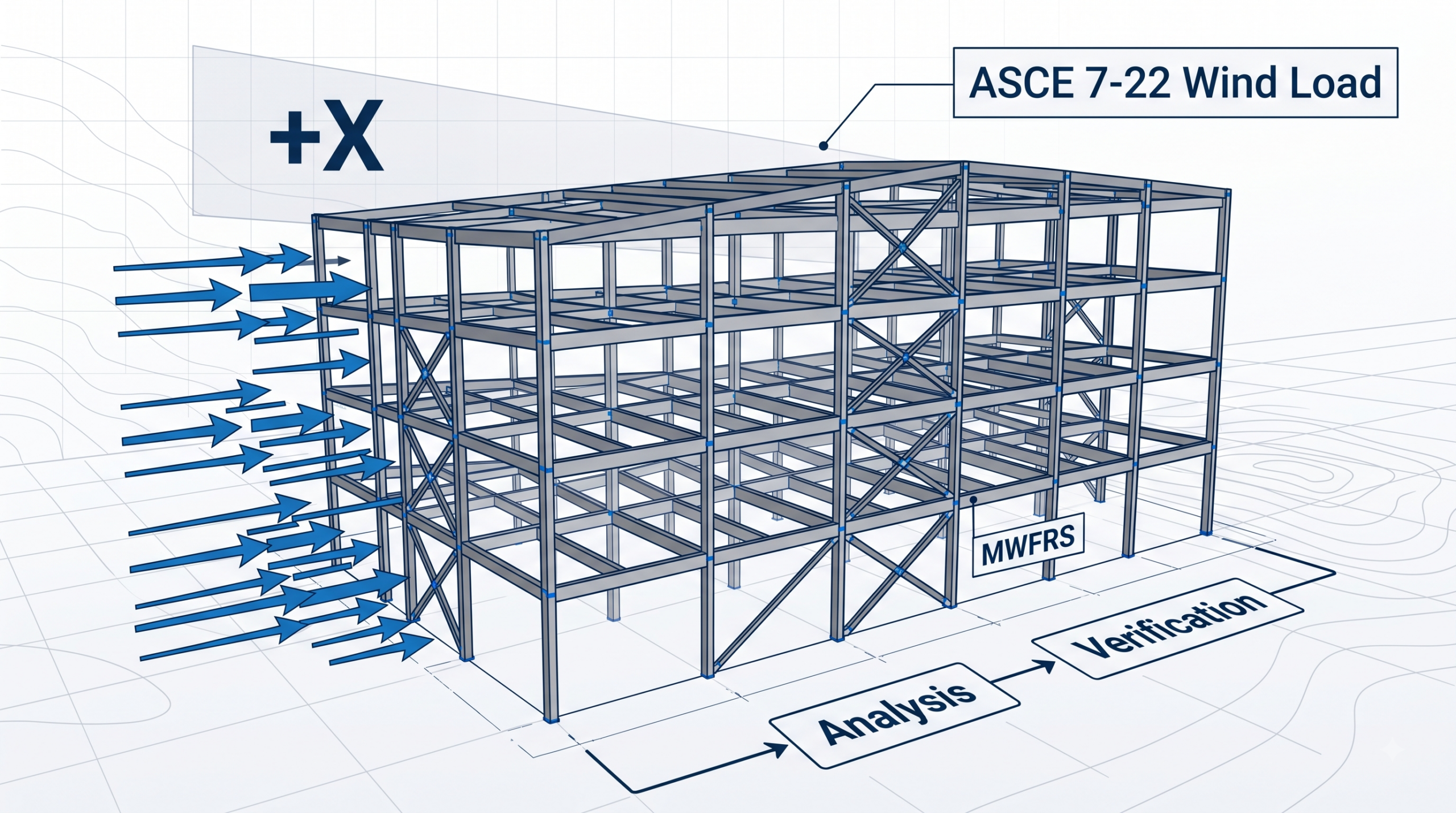
A STAAD Pro ASCE 7-22 wind load workflow becomes much easier once you separate three tasks: defining the wind parameters, generating the structural loads, and checking whether STAAD.Pro applied those loads correctly.
This beginner tutorial follows the logic of Bentley’s official STAAD.Pro 2026 ASCE 7-22 verification example. We will use a small enclosed, flat-roof building and follow the process from the structural model through wind-load generation, analysis, and a simple hand check of the generated joint loads.
The main objective is not to teach you which buttons to memorize. Instead, the goal is to help you understand what STAAD.Pro is doing so you can recognize incorrect inputs and suspicious results before issuing a calculation.
Key Takeaways
- Confirm the ASCE edition before generating wind loads.
- Check Risk Category, basic wind speed, exposure, topography, building dimensions, enclosure, and dynamic characteristics before trusting the generated load.
- STAAD.Pro converts the calculated wind pressure into structural loads based on the model geometry and tributary areas.
- Always inspect the generated loads after running the wind generator.
- Use at least one simple hand check to confirm that pressure × tributary area produces a reasonable nodal force.
- Do not treat successful software analysis as proof that the wind inputs are correct.
- After validating the wind load, review reactions, member forces, overturning, uplift, and the complete structural load path.
What We Will Model in STAAD.Pro
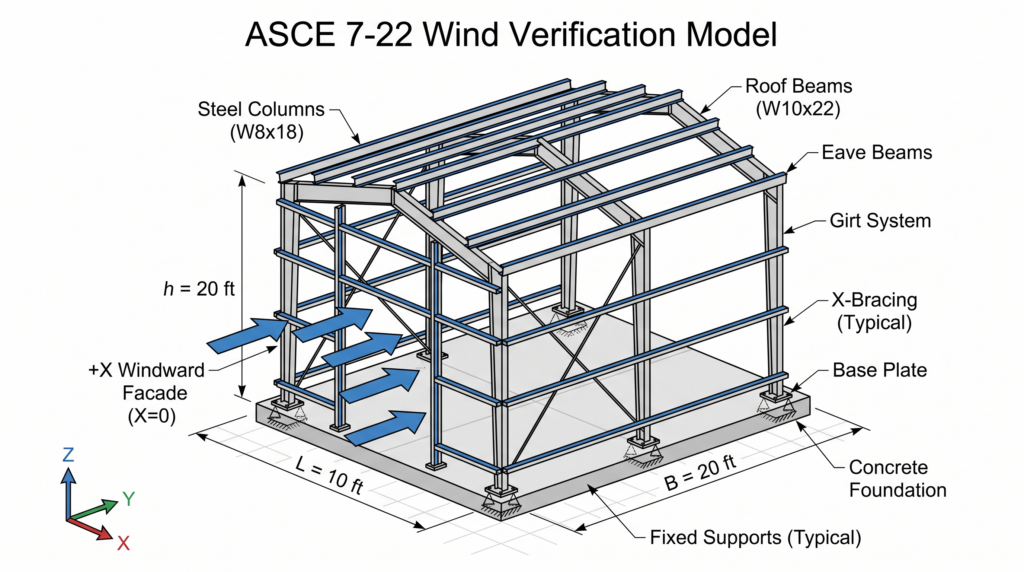
To keep the tutorial reproducible, we will use the basic geometry and wind assumptions from Bentley’s official STAAD.Pro 2026 ASCE 7-22 wind-load verification model.
| Item | Verification Example |
|---|---|
| Wind standard | ASCE 7-22 |
| Wind procedure | Chapter 27 Directional Procedure for MWFRS |
| Building enclosure | Enclosed |
| Roof | Flat |
| Risk Category | II |
| Basic wind speed, V | 108 mph |
| Exposure Category | B |
| Ground elevation | 300 ft above sea level |
| Topographic speed-up | Not considered |
| Building height, h | 20 ft |
| Length along wind direction, L | 10 ft |
| Width normal to wind, B | 20 ft |
| Natural frequency | 2 Hz |
| Wind direction in verification | +X |
Important: These values belong to Bentley’s verification example. Do not reuse 108 mph, Exposure B, Risk Category II, or any other parameter on a real project without determining the correct project-specific values.
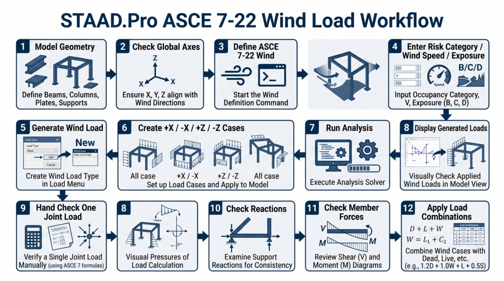
STAAD Pro ASCE 7-22 Wind Load Workflow
- Create and check the structural geometry.
- Confirm the global coordinate directions.
- Define the ASCE 7-22 wind parameters.
- Review the building dimensions and enclosure assumptions.
- Generate the wind-load definition.
- Create the required wind load case.
- Run the analysis.
- Display the generated loads.
- Perform a hand check using pressure × tributary area.
- Review support reactions and member forces.
- Repeat the process for other required wind directions and load cases.
- Combine wind with the other project loads.
Step 1: Build and Check the Structural Model
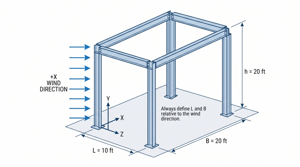
The verification model is a small three-dimensional steel frame. Its overall dimensions are 10 ft in the wind direction, 20 ft normal to the wind direction, and 20 ft high.
For this exercise, the exact steel section is much less important than the building geometry because our main goal is to study the wind-load generator. Bentley’s verification file uses very large W14 members and fixed supports to create a straightforward validation model.
Check the Global Axes First
Before defining wind, confirm the STAAD.Pro global axes. In the verification example, the wind acts in the +X direction.
The building dimension parallel to this wind direction is:
L = 10 ft
The building width normal to the wind is:
B = 20 ft
A common beginner mistake is to swap L and B because the values are interpreted relative to the wind direction rather than simply copied from a plan drawing.
Step 2: Confirm the Wind Design Basis Before Opening the Generator
Do not begin by clicking through the software. First prepare a short wind-design input table.
- ASCE edition
- Risk Category
- Basic wind speed
- Exposure Category
- Ground elevation
- Topographic condition
- Building height
- Building length and width
- Roof type
- Building enclosure
- Natural frequency or rigid/flexible classification
If one of these items is uncertain, stop and resolve it before generating the wind load.
For background on how these parameters fit together, see Engimind’s ASCE 7-22 Wind Loads Explained: A Practical Guide for Junior Structural Engineers.
Step 3: Create the ASCE 7-22 Wind Definition
In STAAD.Pro, create a wind-load definition and select the ASCE 7-22 building wind option available in your installed version.
The exact location and wording of the dialog can vary slightly between STAAD.Pro builds, so focus on the engineering inputs rather than memorizing a screen position.
For the Bentley verification example, enter the following design basis:
- Code: ASCE 7-22
- Basic wind speed: 108 mph
- Risk Category: II
- Exposure: B
- Ground elevation: 300 ft
- Structure type: Building
- Roof: Flat
- Building height: 20 ft
- Length along wind: 10 ft
- Width normal to wind: 20 ft
- Natural frequency: 2 Hz
- Topographic speed-up: Not considered
- Enclosure: Enclosed
Version note: This tutorial is based on the STAAD.Pro 2026 verification model. If an older STAAD.Pro release does not provide the same ASCE 7-22 generator options, confirm the capabilities of that release before continuing.
Step 4: Understand What STAAD.Pro Calculates
Once the inputs are defined, STAAD.Pro calculates the wind-pressure profile required by the selected ASCE procedure.
In Bentley’s verification example, the topographic factor is:
Kzt = 1.0
The ground elevation factor for the assumed 300 ft elevation is approximately:
Ke = 0.989
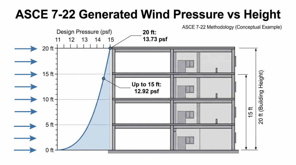
The velocity-pressure exposure coefficient Kz increases with height because the effective wind exposure changes above the ground.
| Height | Kz | Velocity Pressure qz | Design Pressure p |
|---|---|---|---|
| ≤ 15 ft | 0.573 | 16.92 psf | 12.92 psf |
| 15.5 ft | 0.578 | 17.07 psf | 13.01 psf |
| 17.5 ft | 0.597 | 17.63 psf | 13.35 psf |
| 19.5 ft | 0.614 | 18.15 psf | 13.66 psf |
| 20 ft | 0.619 | 18.27 psf | 13.73 psf |
Notice that the design pressure is not perfectly uniform over the full height. Therefore, the generated joint loads near the upper part of the building also reflect the changing pressure.
Step 5: Generate the +X Wind Load Case
After creating the wind definition, generate a wind load case for the +X direction.
In the Bentley verification input, STAAD.Pro ultimately writes the following load command:
LOAD 1 LOADTYPE Wind TITLE LOAD CASE 1
WIND LOAD X 1 TYPE 1
STAAD.Pro also creates a generated-data block containing the ASCE 7-22 parameters and an intensity-versus-height definition.
Do not manually edit the STAAD.Pro generated-data block unless you fully understand the consequences. If an engineering input is wrong, return to the load-definition workflow and correct the source parameter.
For a real building, one wind direction will rarely complete the project. Create the additional project-required directions and cases after validating the basic setup.
Step 6: Run the Analysis
Run the STAAD.Pro analysis after the wind load has been generated.
For learning and quality control, request load-data output where practical. Bentley’s verification model uses:
PERFORM ANALYSIS PRINT LOAD DATAThis output makes it easier to see the equivalent joint loads that STAAD.Pro created.
Step 7: Inspect the Generated Wind Loads
This is one of the most important steps in the entire tutorial.
Do not jump directly from “Analysis Completed” to member design. First display or review the generated wind loads.
Ask the following questions:
- Are the loads acting in the expected global direction?
- Are the loaded nodes located on the correct windward surface?
- Does the load generally increase with height?
- Are corner-node loads smaller than interior-node loads where tributary areas are smaller?
- Is the total force roughly consistent with pressure × projected area?
If the load arrows point in the wrong direction or appear on unexpected portions of the frame, stop and review the model geometry and wind definition.
Step 8: Perform a Simple Hand Check
You do not need to reproduce the entire ASCE wind chapter by hand to perform a useful software check.
A simple tributary-area calculation can verify whether the generated nodal loads have the correct order of magnitude.
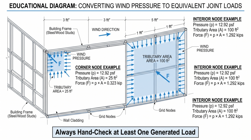
Example A: Corner Node
For a lower corner node, the tributary dimensions in Bentley’s example are approximately:
10 ft / 2 × 10 ft / 2 = 25 ft²
The corresponding lower-level design pressure is:
p = 12.92 psf
Therefore:
F = pA
F = 12.92 × 25 = 323 lb ≈ 0.323 kip
STAAD.Pro reports approximately:
0.32 kip
The agreement is excellent for this verification case.
Example B: Interior Node
An interior node has a tributary area of:
10 ft × 10 ft = 100 ft²
Using the same 12.92 psf design pressure:
F = 12.92 × 100 = 1,292 lb = 1.292 kips
STAAD.Pro reports approximately:
1.29 kips
Again, the generated load matches the simple hand calculation closely.
Bentley Verification Results
Bentley’s official STAAD.Pro 2026 verification compares calculated reference joint loads with STAAD.Pro output.
| Node | Reference | STAAD.Pro |
|---|---|---|
| 1 | 0.323 kip | 0.32 kip |
| 2 | 0.646 kip | 0.65 kip |
| 5 | 0.646 kip | 0.65 kip |
| 6 | 1.292 kips | 1.29 kips |
| 9 | 0.323 kip | 0.32 kip |
| 10 | 0.646 kip | 0.65 kip |
| 13 | 0.334 kip | 0.33 kip |
| 15 | 0.667 kip | 0.67 kip |
| 17 | 0.334 kip | 0.33 kip |
The differences are negligible in the official verification example. This provides a useful benchmark for understanding how the STAAD.Pro wind generator converts the ASCE pressure calculation into equivalent structural joint loads.
Step 9: Review Support Reactions
After validating the generated load itself, move to the global structural response.
Review the support reactions and ask whether they make physical sense.
- Is the total horizontal reaction consistent with the applied wind force?
- Does the structure develop the expected overturning response?
- Are uplift reactions appearing where expected?
- Are reactions balanced between frames in a reasonable way?
- Does the sign convention match the applied wind direction?
A reaction imbalance can indicate modeling problems, disconnected members, incorrect supports, unintended releases, or an incorrect wind-load application.
Step 10: Review Member Forces and Deflections
Next, review the members that form the lateral load path.
- Column axial forces
- Column bending moments
- Beam and frame moments
- Brace forces where applicable
- Story displacement
- Overall lateral deflection
Do not review only the largest number in the result table. Instead, trace the force from the wind-loaded surface through the structural system and into the foundations.
For a broader explanation of this concept, see Structural Load Paths Explained.
Step 11: Create the Other Required Wind Directions
The Bentley verification example focuses on +X wind because its purpose is software validation.
An actual structural analysis normally requires additional wind directions and load cases according to the selected ASCE procedure and project requirements.
Depending on the building and analysis setup, you may need to consider:
- +X wind
- −X wind
- +Z wind
- −Z wind
- Required torsional or load-case effects
- Other cases required by the selected ASCE wind procedure
Do not simply copy a +X load case and reverse its sign without confirming the pressure distribution and building geometry for the opposite wind direction.
Step 12: Add Wind to the Load Combinations
Generating the wind load does not complete the structural design. Next, combine the wind effects with dead, live, roof, snow, seismic, and other applicable loads using the project’s adopted load combinations.
Different wind combinations may control different parts of the structure.
- Frame member strength
- Foundation overturning
- Anchor-bolt tension
- Column base uplift
- Lateral displacement
- Connection design
For more detail, see Load Combinations Explained: ASCE 7 & ACI 318.
Common STAAD Pro ASCE 7-22 Wind Load Mistakes
- Using the wrong ASCE edition: A model created for ASCE 7-16 should not automatically be treated as an ASCE 7-22 model.
- Swapping L and B: Building dimensions depend on the selected wind direction.
- Using the wrong Risk Category: Verify the design basis before entering the wind speed.
- Selecting Exposure B without checking the terrain: Use the actual project surroundings and ASCE requirements.
- Ignoring topography: Do not leave Kzt at a default value without considering the site.
- Entering the wrong elevation: Ground elevation can affect the calculated velocity pressure.
- Using the wrong enclosure condition: Internal pressure affects the final wind pressure.
- Confusing rigid and flexible behavior: Confirm the building’s dynamic characteristics.
- Generating wind on incorrect model geometry: The load generator depends on the analytical model.
- Checking only “Analysis Completed”: Always inspect the generated loads.
- Skipping the hand check: One tributary-area calculation can reveal major setup errors.
- Reviewing member forces before validating loads: Correct analysis of an incorrect load is still incorrect.
- Manually changing generated STAAD data: Correct the engineering input at its source whenever possible.
- Using only one wind direction: Create all project-required wind cases.
Engineering Manager’s Note
When reviewing a software-generated wind load, I first look at the model with the load arrows displayed. I want to see the direction, loaded surface, load distribution with height, and relative magnitude before I look at member stresses or design ratios.
Then I perform one simple pressure-times-area calculation. If the software load is in the same range, I continue the review. If it is not, I stop and find the reason.
This habit is much faster than trying to diagnose an incorrect wind definition after hundreds of member checks have already been generated.
Beginner QC Checklist
- ✓ STAAD.Pro version confirmed
- ✓ ASCE 7-22 selected
- ✓ Global axes checked
- ✓ Wind direction confirmed
- ✓ Risk Category checked
- ✓ Basic wind speed documented
- ✓ Exposure Category justified
- ✓ Ground elevation confirmed
- ✓ Topography reviewed
- ✓ Building dimensions verified
- ✓ Enclosure classification checked
- ✓ Dynamic classification reviewed
- ✓ Generated load visually inspected
- ✓ At least one nodal force hand-checked
- ✓ Support reactions reviewed
- ✓ Member forces reviewed
- ✓ Deflection reviewed
- ✓ Other wind directions created
- ✓ Wind load combinations added
- ✓ Calculation independently reviewed
Where to Find Bentley’s Verification Model
Bentley’s STAAD.Pro 2026 documentation states that the ASCE 7-22 wind verification file is typically installed with the software under the Public Documents sample directory.
C:\Users\Public\Public Documents\STAAD.Pro 2026\Samples\
Verification Models\06 Loading\Wind Load\
ASCE 7-22 Wind Load Generation on Building.STD
If the sample exists in your installation, open it and compare the input file, generated wind data, load arrows, and analysis output with the workflow described in this article.
Conclusion
A STAAD Pro ASCE 7-22 wind load analysis should never be a black-box exercise.
Start by confirming the engineering inputs. Next, generate the wind definition and load cases. After running the analysis, visually inspect the generated loads and perform a simple tributary-area hand check. Only then should you move on to reactions, member forces, deflections, load combinations, and design checks.
The software can automate a large amount of repetitive calculation, but the engineer still owns the assumptions, model geometry, load path, and final interpretation of the results.
Sources and Further Reading
- Bentley Systems — STAAD.Pro 2026: ASCE 7-22 Wind Load Generation on Building Verification
- Bentley Systems — STAAD Structural Analysis and Design
- ASCE — ASCE/SEI 7-22
- ASCE Hazard Tool
- ASCE — Introduction to ASCE 7-22 Wind Loads
Technical Disclaimer
This tutorial is intended for educational use. The worked parameters are based on Bentley’s software verification example and are not project design values.
Always verify the locally adopted building code, ASCE edition, project wind criteria, site hazard data, exposure, topography, enclosure, structural geometry, applicable wind procedure, and STAAD.Pro version before using generated wind loads for an actual structure.
“`