
Part 1: The Three Brothers of Force and the “Load” Backpack
How do the massive bridges we cross, the towering roofs over our heads, and the high-speed elevated highways we drive on stand perfectly still without a single wobble? Welcome to the world of structural engineering! The ultimate goal of this discipline can be summed up in one simple mission: to guide every single downward force safely through the structure and dissipate it harmlessly into the earth.
To understand how buildings stay standing, we must first introduce the “Three Brothers of Force” that constantly battle inside every structure, along with the invisible highways they travel.
1. The Three Sisters of Stress (Compression, Tension, and Shear)
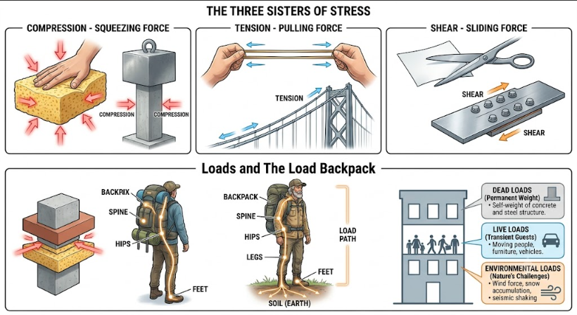
You can easily visualize the stresses a building experiences using simple everyday objects :
- Compression (The Squeezing Force): Take a soft sponge and squeeze it between your palms . The sponge deforms, shortening and flattening. This squeezing action is compression . The sturdy columns of a skyscraper or the legs of your chair are under constant compression, fighting gravity every second .
- Tension (The Pulling Force): Now, take a rubber band and pull it tight from both ends . The rubber band becomes thinner and longer, resisting your pull until—if you pull too hard—it snaps . This stretching action is tension . The steel cables holding up massive suspension bridges or the tight strings of an acoustic guitar are primary examples of elements designed to resist tension .
- Shear (The Slideway Force): Think of how scissors cut paper . The two blades pass closely by each other in opposite directions, sliding and tearing the paper apart . This slicing, sliding-past action is shear . When an earthquake violently shakes the ground, the walls of a building undergo severe shear forces as the top and bottom try to slide in opposite directions .
2. Loads: The Heavy Backpacks of a Structure
Every bit of weight a structure has to carry is called a “Load.” Engineers categorize these loads based on their movement and predictability :
- Dead Loads (The Permanent Weight): This is the self-weight of the structure itself . It includes the concrete walls, the steel beams, the pipes, and the permanent flooring that stay in place for the entire lifespan of the building .
- Live Loads (The Transient Guests): These are temporary, moving weights . The people walking across a floor, the cars driving on a bridge, and the furniture rearranged in an office are all live loads because their position and magnitude change over time .
- Environmental Loads (Nature’s Challenges): These are unpredictable forces imposed by weather and geology . They include heavy wind gusting against a glass facade (wind load), thick snow piling up on a roof (snow load), and sudden tectonic accelerations (seismic load) .
3. The Load Path: The Invisible Highway
Engineers often compare a structure to a backpacker carrying a heavy load . Just as the weight of the backpack must travel from your shoulders, down your spine, through your hips, and down your legs into your feet, a building must have a clear, continuous path for forces to travel down to the soil . This is known as the “Load Path.”
A great analogy is a roof rainwater gutter system . Rainwater falls on the roof, gathers in the gutters, flows down the downspouts, and drains into the ground . Forces behave exactly the same way .
Let’s trace a typical load path of a person standing on the second floor of a building :
- The person’s weight (live load) is first supported by the floor slab .
- The slab transfers this weight to the closely spaced, parallel floor joists .
- The joists carry this force and pass it on to the primary horizontal beams .
- The beams collect the weight from multiple joists and channel it into the vertical columns .
- The columns, bearing tremendous compressive stress, push the load straight down into the underground foundation .
- Finally, the foundation spreads the concentrated weight over a wide area, letting the soil (ground) absorb and dissipate the force without sinking .
If any link in this chain is broken or too weak, the load cannot reach the ground, leading to excessive cracking, sagging, or catastrophic collapse .
Part 2: The Structural Elements and the Three Paradigms of Safety
Now that we understand how forces flow, let’s look at the basic building blocks (elements) engineers use to frame buildings, and how our philosophy of structural safety has evolved over the generations.
1. Structural Members and Their Superpowers
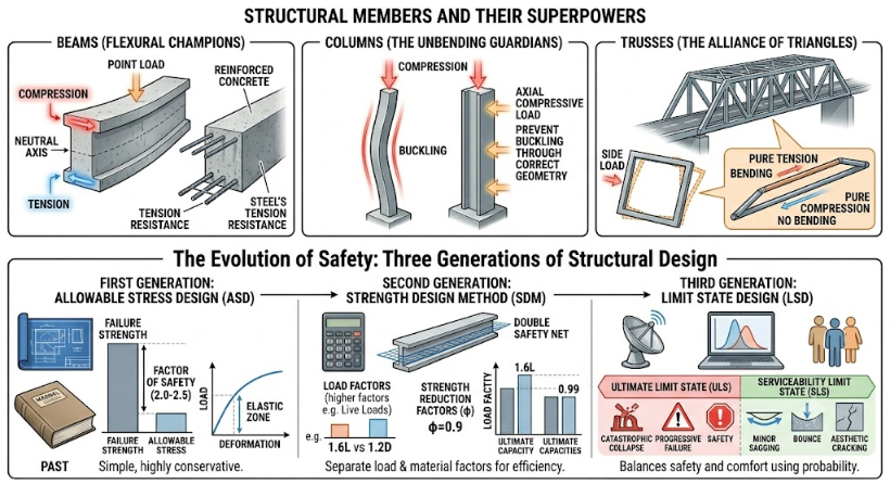
- Beams (The Flexural Champions):Beams are horizontal members designed to support loads applied perpendicular to their length . When you place a heavy load on a beam, it bends downward into a U-shape (positive curvature) . This bending creates a dual-stress environment inside a single beam :
- The top half of the beam is squeezed together under compression .
- The bottom half of the beam is stretched apart under tension .
- The exact middle line (neutral axis) experiences zero stress .Concrete is fantastic at resisting compression but is incredibly weak under tension . To prevent concrete beams from cracking and snapping on the bottom, engineers place tensile steel reinforcement bars (rebars) on the tension side . This creates “reinforced concrete”—one of the most successful material marriages in human history .
- Columns (The Unbending Guardians):Columns are vertical members that bear axial compressive loads parallel to their length . Their main enemy is “Buckling”—a sudden, dramatic sideways bending that happens when a slender column is overloaded from the top before the material itself actually crushes . To prevent buckling, columns must be designed with sufficient cross-sectional thickness and straight alignment .
- Trusses (The Alliance of Triangles):Look at a railway steel bridge or the roof of a large sports stadium; you will see a network of steel bars arranged in triangles . Why triangles and not squares? A square frame can easily tilt and deform into a parallelogram when pushed from the side . A triangle, however, is geometrically rigid; its shape cannot change unless the length of its sides physically changes . In a truss, every single bar is spared from complex bending; they only experience pure, simple tension or compression . This allows us to span immense distances using very light materials .
2. The Evolution of Safety: Three Generations of Structural Design
How do engineers decide how thick a beam or column needs to be? Over the past century, design philosophies have evolved dramatically :
First Generation: Allowable Stress Design (ASD)
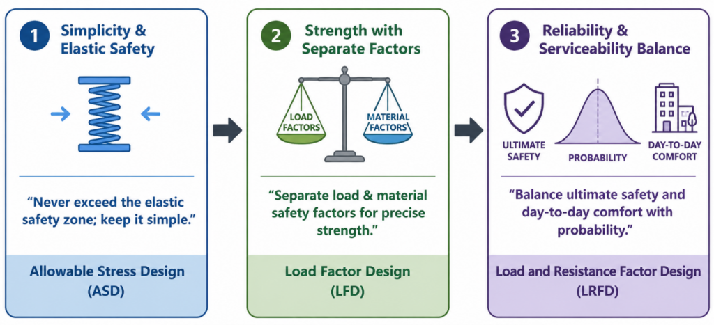
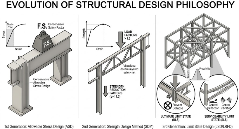
- The Philosophy: “We must ensure that the stress in our materials remains well within the elastic range—where materials behave like a perfect spring and return to their original shape when unloaded.”
- The Method: Engineers calculate the maximum stress at which a material fails (its yield strength) and divide it by a thick, conservative factor of safety (usually 2.0 to 2.5). The actual stresses under normal loads must never exceed this “allowable stress” limit.
- The Verdict: While incredibly simple and reliable, it is highly conservative. It ignores the material’s post-yield reserve strength and treats highly predictable loads (like a building’s own concrete weight) and highly unpredictable loads (like a sudden hurricane wind) with the exact same blanket factor of safety.
Second Generation: Strength Design Method (SDM)
- The Philosophy: “Let’s design for the actual, ultimate strength of the material right before it permanently deforms or breaks, but apply scientific safety factors to both the loads and the materials.”
- The Method: It uses a double-layered safety net:
- Load Factors: Normal loads are multiplied by factors greater than 1.0 (e.g., applying a higher factor to highly volatile live loads than to steady dead loads) to simulate extreme overload scenarios.
- Strength Reduction Factors (φ): The ultimate capacity of the member is multiplied by a reduction factor less than 1.0 to account for minor construction defects or material variations.
- The Verdict: It creates much more material-efficient, lighter structures. However, because the structures became so slim, buildings designed purely for strength occasionally suffered from “serviceability” issues—meaning the building was perfectly safe from collapse, but the floors sagged or vibrated so much that occupants felt uncomfortable.
Third Generation: Limit State Design (LSD)
- The Philosophy: “We must treat structural safety and daily human comfort as two separate, equally important ‘Limit States’ using advanced probability and statistics.”
- The Method: It splits design criteria into two distinct boundaries:
- Ultimate Limit State (ULS): Focuses on catastrophic safety. It ensures the structure will not collapse, overturn, or suffer progressive failure under extreme, once-in-a-lifetime events.
- Serviceability Limit State (SLS): Focuses on daily functionality and comfort. It strictly limits minor deflections, bounce, aesthetic cracking, and annoying vibrations during normal, day-to-day use.
- The Verdict: By utilizing individual partial safety factors grounded in real-world statistical data, LSD achieves the ultimate balance of safety, structural efficiency, and human comfort. It is the modern global standard for complex mega-structures.
Part 3: The Golden Rules of Force Flow, Common Mistakes, and When Structures Scream
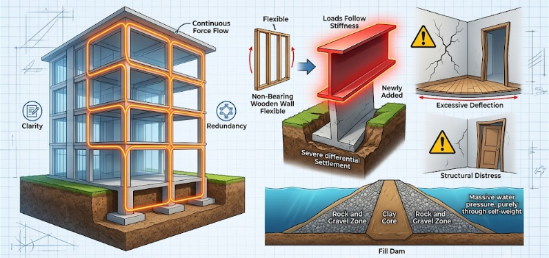
In our final section, let’s explore the golden rules of designing a safe load path, look at common blunders beginner engineers make, and learn how to read the warning signs a building displays when it is in distress.
1. The Three Golden Rules of Force Flow
When laying out a structural design, engineers must always obey three fundamental laws of force transmission :
- Clarity: Force paths should be as direct and straight as possible . Curvy, meandering paths force members to twist and bend unnecessarily, which requires much thicker and more expensive materials .
- Continuity: There must be zero gaps in the structural chain . Every slab must feed a joist, every joist a beam, every beam a column, and every column a footing . A “dead end” in a load path creates a catastrophic stress concentration .
- Redundancy (The Alternate Path): Never rely on a single line of defense . If a vehicle crashes into a ground-floor column of a parking garage and destroys it, a redundant structure will not collapse . Instead, the loads will automatically redirect themselves through neighboring beams and columns using an Alternative Load Path, saving lives .
2. Common Beginner Mistakes in the Field and the Office
Even with advanced computers, minor oversights in physical behavior can lead to serious field failures :
- “Loads Follow Stiffness” (The Magnetic Pull of Rigidity):Forces are incredibly smart; they do not distribute themselves evenly . Instead, loads automatically rush toward the stiffest, most rigid path available .Imagine a homeowner removing a flexible, non-bearing wooden wall and deciding to “strengthen” the house by installing an extremely rigid steel H-beam in its place. Because the steel beam is incredibly stiff compared to the surrounding wood framing, the forces from the upper floors will violently migrate toward this single steel beam. If the floor underneath that beam wasn’t designed for such a concentrated force, it can punch straight through the floor, causing localized structural failure .
- Assuming “Tight is Tight Enough” in Bolted Connections:Many beginner engineers assume that turning a wrench until a bolt cannot move is the safest practice . In reality, under-tightened bolts will loosen under daily vibrations, while over-tightened bolts stretch past their yield point, damaging the steel threads and making them prone to snapping suddenly under load . Bolted connections must always be tightened to precise torque values using calibrated torque wrenches .
- Underestimating Geotechnical “Soil Play”:A building is only as good as the dirt it sits on . Ground soil behaves like a giant, slow-moving sponge . If an engineer fails to analyze the soil properly, the building can suffer from “differential settlement”—where one side of the foundation sinks faster than the other . This rotates the columns, jams doors, and cracks concrete .
3. When Structures Scream: Reading the Warning Signs
Buildings rarely collapse without warning . When a load path is overstressed, the structure will display visible “SOS” signals :
- Diagonal Cracks in Drywall or Concrete Walls: A diagonal crack (usually at a $45^\circ$ angle) is a clear sign of shear distress, often caused by one side of the foundation settling lower than the other .
- Saggy, Bouncy, or Creaking Floors: If walking across a room feels like stepping on a trampoline, the horizontal beams have exceeded their serviceability limit state and are deflecting too much under live loads .
- Sticky Doors and Windows: When a door or window suddenly binds, sticks, and refuses to close smoothly, the surrounding structural frame is warping . This means the load-bearing columns are shortening or tilting, distorting the rectangular frame into a parallelogram .
4. Dams: Holding back Oceans with Just Dirt and Rock
To appreciate structural engineering on a grand scale, look at a Fill Dam . These massive structures hold back millions of tons of water without using a single ounce of steel or concrete . They achieve this through smart material zoning :
- The Clay Core: The center core of the dam is made of highly compacted, sticky, impermeable clay. Clay particles bind together so tightly that they create an absolute water barrier, stopping leaks.
- The Rock and Gravel Zone: Since wet clay has very little structural strength, engineers sandwich the clay core between massive slopes of heavy gravel, sand, and rock.
This entire mountain of soil resists the enormous hydrostatic pressure of the river purely through its own self-weight and the internal friction of the rock particles, governed by the classic shear strength equation:
τ=c+σtanϕ
where:
- τ (tau) = shear strength or shear resistance of the soil
- c = cohesion of the soil (e.g., clay cohesion)
- σ (sigma) = effective normal stress acting on the potential failure surface
- φ (phi) = internal friction angle of the soil or rock particles
This relationship shows that the resistance to sliding is provided by two mechanisms: the cohesion between particles and the friction generated by the normal stress acting on the soil mass. It is a stunning display of utilizing nature’s simplest materials to tame some of the planet’s most powerful forces.
FAQ (Frequently Asked Questions)
Q1: Why is concrete almost always reinforced with steel rebars?
Concrete has excellent compressive strength (it can bear a lot of squeezing weight), but its tensile strength is only about 10% of its compressive capacity . When a concrete beam bends, its bottom half stretches under tension and cracks easily . Steel is incredibly strong under tension . By embedding steel rebars in the tensile zones of concrete members, we combine the best of both materials: concrete handles the squeezing, and steel handles the pulling .
Q2: What is the difference between strength and stiffness?
While they sound similar, they are completely different concepts:
- Strength is a material’s capacity to resist an applied force without breaking or permanently deforming .
- Stiffness is a material’s resistance to elastic displacement or bending under a load . A thin steel rod can be incredibly strong (it won’t break when you pull it), but it is very flexible (it lacks stiffness and bends easily) . Safe structures must have both: enough strength to prevent collapse (ULS) and enough stiffness to prevent annoying bouncing or sagging (SLS).
Q3: What is “Alternative Load Path” and why does it matter?
An Alternative Load Path is a design strategy used to prevent progressive collapse . If a critical load-bearing column is destroyed (due to an accident, explosion, or seismic impact), a non-redundant building will collapse like a house of cards . However, if the structure has redundant paths, the load previously carried by the destroyed column will immediately find alternative, adjacent routes (traveling sideways through rigid beams and neighboring columns), keeping the building standing long enough for occupants to evacuate .