
Introduction
Load combinations are a fundamental concept junior structural engineers must master. In practice, loads do not act in isolation — dead load, live load, wind, earthquake, snow, flood effects and others can act together in complex ways. Design codes use combinations to represent realistic simultaneous effects and to ensure safety and serviceability. This article explains the concept at a beginner level, contrasts strength and serviceability approaches, summarizes how ASCE 7 and ACI 318 expect designers to account for combinations in concrete design, and provides a clear step-by-step workflow and checklists you can use on real projects.
Key takeaways
- Load combinations represent realistic simultaneous actions and assign factors to account for uncertainty and desired reliability.
- Strength checks (LRFD/factored) and serviceability checks (ASD/unfactored or differently factored) use different numerical treatments but the same selection principle: apply the combination that produces the most unfavorable result for the limit state.
- ASCE 7 defines load types and provides the combination framework; ACI 318 references factored combinations for concrete member design. Always consult the code text for exact factors and equations.
- Follow a consistent workflow: list loads, set up load cases, choose the required code/approach, apply combinations, identify controlling cases, and document assumptions (especially live-load reductions).
1. What are the common load types?
Before combining loads you need to identify which loads apply to your structure. At a glance:
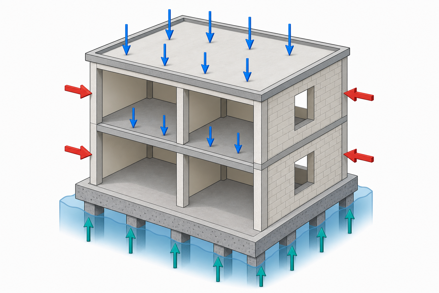
- Gravity: dead loads (self-weight, finishes), live loads (occupancy, movable loads), roof live, snow.
- Lateral and environmental: wind, earthquake (seismic), hydraulic forces (flood, tsunami), rain and hydrostatic pressures.
- Other: thermal effects, soil and earth pressure, construction loads, cranes and impact loads, foundation uplift/buoyancy.
Some loads are project- or location-specific (e.g., flood zones, high seismicity) and must be handled according to local requirements and the project brief.
2. The concept behind load combinations
Why combine loads?
Real structures experience multiple actions simultaneously. Codes use combinations to reflect probable simultaneous extremes and to build safety margins into design. Load factors increase or decrease the magnitude of individual actions in a combination to account for uncertainties in magnitude, occurrence probability, and modeling error.
Strength vs serviceability
Two common design philosophies drive how combinations are formed:
- LRFD (Limit State / Strength design): uses factored loads (greater than nominal) to check capacity. Factors account for uncertainty and ensure reliability for ultimate limit states like collapse, major yielding, or loss of stability.
- ASD (Allowable Stress / Serviceability checks): often uses unfactored or differently factored combinations aimed at serviceability limit states such as deflection, cracking, or vibration. The goal is usability and comfort, not ultimate capacity.
Regardless of philosophy, the practical rule is the same: for each limit state pick the combination that gives the most unfavorable effect (largest moment, shear, deflection, etc.).
3. How ASCE 7 and ACI 318 use load combinations (conceptual)
ASCE 7 is the U.S. reference for defining loads and prescribing how actions should be combined. It sets out the national framework for gravity, lateral, and special loads and provides combination forms for strength and serviceability checks. ACI 318 is the concrete code and expects designers to use appropriate factored load combinations when checking concrete members for strength and detailing. ACI often refers to the general combination framework rather than restating environmental load definitions.
Important: this article explains concepts and workflows; do not substitute it for the actual code. For exact equations, load factors, and specific exceptions, consult the ASCE 7 and ACI 318 documents required by your jurisdiction.
4. LRFD (strength) vs ASD (serviceability) — practical differences
In everyday design:
- Use factored LRFD combinations to size members and determine reinforcement/section strength. LRFD combinations will often inflate live or environmental loads and may include reduction rules for some companion actions.
- Use ASD or serviceability-type combinations to check deflections, crack widths, vibrations, and deformations. These combinations typically use characteristic (unfactored) values or smaller factors so the structure remains usable under normal conditions.
A practical tip: your contract or local code will state whether LRFD, ASD, or a hybrid is required. If in doubt, ask the project structural lead or the client’s engineer of record.
5. Practical workflow: step-by-step
- Identify all relevant loads. Review project documents, ASCE 7 chapters relevant to your location, geotechnical report, mechanical loads, and owner requirements. Create a checklist of loads to be modeled.
- Confirm code edition and design philosophy. Note the ASCE 7 edition and ACI 318 edition required by contract and which design method (LRFD, ASD) to use.
- Create separate load cases in your analysis model. Each load type (dead, live, snow, wind, seismic, flood, etc.) should be modeled as a separate case so you can combine them programmatically or manually.
- Apply the code’s combinations for the appropriate limit state. For strength checks use factored combinations; for serviceability checks use the serviceability combinations. Also apply any project-specific or special-event combinations (for example, flood + wind guidance or crane load rules).
- Identify controlling combinations for each member and limit state. Document which combination controls bending, shear, axial, and deflection for each member and why.
- Document reductions and assumptions. If you apply live-load reductions or tributary-area adjustments, record the calculations and justification per code clauses and project assumptions.
- Validate software outputs. Run a manual spot-check on a few critical combos to ensure your analysis package is producing the expected enveloping actions.
6. Example scenarios (conceptual)
Two short conceptual examples that illustrate how combinations influence result envelopes:
Example A — Gravity-dominated member
A midspan of a continuous concrete beam may be controlled by gravity loads (dead + live). Factored strength combinations increase these values and therefore govern bending and shear design. However, a lateral load combination (wind or seismic) could increase axial effects at supports and change end moments; check both types of combinations for different failure modes.
Example B — Lateral-dominated member
A bracing element or a shear wall in a high-seismic region will be governed by seismic combinations for strength checks. The associated axial and overturning effects from earthquake combinations can produce different axial force and moment patterns than wind; therefore detailing (e.g., development lengths, confinement) must consider the controlling seismic combination.
7. Common pitfalls and practical tips
- Missing special loads: Don’t forget temporary construction loads, crane loads, hydrostatic/flood uplift, or thermal gradients when they apply. These can control critical details.
- Misapplying live-load reductions: Live-load reduction rules are area-dependent and often applied at the member level, not uniformly. Applying reductions incorrectly can under-predict governing moments or shears.
- Assuming software is correct without checking: Many analysis packages auto-generate combinations. Verify a few manually, especially when multiple load factors or special-case rules (flood, seismic complements) apply.
- Combining excluded loads: Some combinations do not pair certain environmental loads together (codes often restrict pairing of rare events). Always check code guidance on which loads are mutually exclusive or conditional.
- Poor documentation: Failing to list the exact code edition, reductions, and assumptions in your calculation notes can create review delays or liability issues.
8. Quick checklist before submitting calculations
- Confirm the required code editions and design method are stated on the cover sheet.
- List every load case used and the source for each load magnitude.
- Record any reductions or special treatments (live-load reduction method, tributary areas, flood treatment).
- Show the controlling combination for each member and limit state with a short explanation.
- Include at least one manual spot-check comparing software outputs for a typical controlling combo.
Conclusion
Load combinations are the practical bridge between real-world actions and safe, code-compliant design. Mastering them requires clear identification of loads, understanding which limit state you are checking (strength vs serviceability), correctly applying the code-prescribed combinations, and documenting assumptions. For junior engineers the most valuable habits are: keep loads and cases organized, validate software with manual checks, and always cite code editions and rationales in your calculations. When in doubt, refer to ASCE 7 and ACI 318 and consult experienced colleagues or the engineer of record.