
Introduction
This STAAD.Pro continuous beam tutorial is written for junior engineers and students who want a compact, practical workflow to create and check a 3-span continuous beam. By following the steps below you will: set up units and geometry, assign materials and sections, apply self-weight plus distributed and point loads, run a linear static analysis, and perform quick verification checks so you can trust your results.
Key takeaways
- Work in small steps: set units, check connectivity, then add loads.
- Use Form Member (or Auto Form Member) to treat adjacent beam elements as continuous for post-processing.
- Check equilibrium (sum of loads ≈ sum of reactions) and view deflected shape before trusting detailed results.
- Common beginner mistakes: disconnected nodes, wrong units, incorrect load direction, and double-counting self-weight.
Software and setup checklist
- STAAD.Pro version and modeler: pick either Analytical or Physical Modeler and stay consistent for the exercise. This tutorial uses the Analytical/Beam workflow but the steps apply in Physical Modeler too.
- Set units first (e.g., meters and kN). Write them down and keep them visible while modelling.
- Save an initial baseline file (model_v1.std) before you begin; save a ‘verified’ copy after a successful run.
Example problem (practical values)
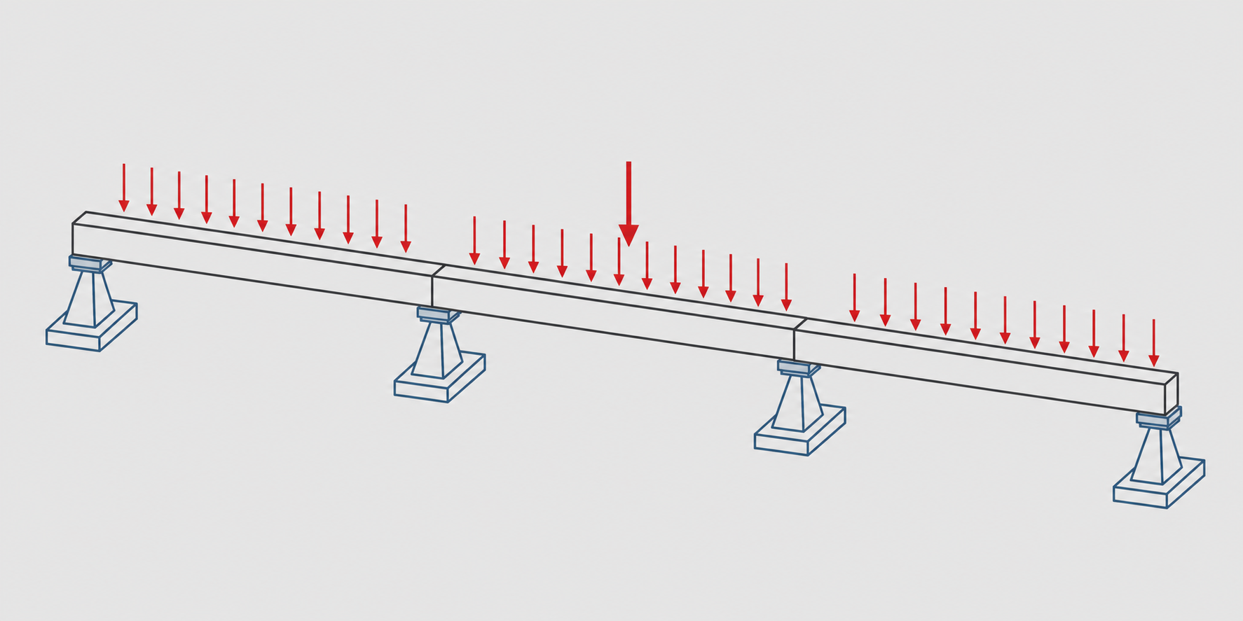
We will model a 3-span continuous beam with spans: 4.0 m, 5.0 m, 4.0 m (total length 13.0 m). Supports at x = 0, 4.0, 9.0 and 13.0 m. Use a standard section from STAAD library (for example a beam section you select), apply self-weight, a uniform live load w = 5.0 kN/m on all spans, and a concentrated point load P = 20.0 kN at the mid-span of the middle span (x = 6.5 m). Units: meters, kN.
Step 1 — Sketch and modelling logic
Sketch before you model: draw the three spans on paper. Decide modelling logic:
- Nodes at each span end (0, 4, 9, 13 m).
- Beam elements connecting consecutive nodes: three member elements for the three spans.
- Form a continuous member grouping those three beam elements so STAAD.Post processors treat it as one continuous beam for bending continuity and design checks.
- Apply distributed loads to members, and point loads at specific nodes (or at inserted intermediate nodes if the load doesn’t coincide with an existing node).
Step 2 — Create nodes and members (geometry)
- Create joints at X = 0.0, 4.0, 9.0, 13.0 (Y = 0, Z = 0 if modelling in the X-direction).
- Use the Add Beam tool to connect joint 1–2, 2–3 and 3–4.
- Tip: insert an extra node at x = 6.5 m for the mid-span point load if you prefer point loads to be at nodes; otherwise STAAD can accept mid‑member point loads specified by distance from the start of the member.
- Input check: open the Joint table and confirm coincident coordinates for joints that must be connected.
Step 3 — Assign member properties and materials
- Choose a section from STAAD’s section database (or define a custom section). For beginners, use a standard section to avoid manual property errors.
- Select a material (e.g., Concrete or Steel) from the library. Confirm the material properties shown (E, density). If you change units, re-check that the material constants are still correct.
- Check section orientation (beta angle) and local axes for non‑symmetric sections so distributed loads act correctly along the intended local axis.
Step 4 — Define supports and boundary conditions
- Assign supports (for a simple continuous beam): vertical restraint at supports (usually UY fixed). For 2D beam modelling you may restrain translations in the out‑of‑plane direction and rotations if needed by your analysis type—choose minimal restraints to prevent rigid body motion.
- Input check: inspect support symbols in the model view and run the Support Summary table (print or view) to verify the correct DOFs are constrained at each support.
- Tip: if the model moves rigidly in the deflected shape, you likely missed a restraint or used inconsistent DOFs.
Step 5 — Apply loads and create load cases
- Enable self-weight (use STAAD’s self-weight toggle) and set direction (usually negative Y or Z depending on your model orientation). Do not also add manual manual self-weight unless you intend to double-count it.
- Create load cases: Dead (self-weight), Live (uniform distributed load), and a LoadCase for the point load. Example: Live = uniform w = 5.0 kN/m on each member; PointLoad = 20.0 kN downward at mid-span node of the middle span.
- Confirm load directions and sign convention with a quick test: apply a single downward point load and run the model to see a single reaction in the expected support.
Step 6 — Form members for continuous-beam behavior
- Select the three beam elements and use Form Member (or Auto Form Member) to combine them into a single continuous member. This helps STAAD treat the continuous element properly in bending/moment diagrams and design modules.
- Input check: view the Member table to confirm the formed member ID and that the section assignment is consistent across the formed member.
Step 7 — Run analysis
- Start with a linear static analysis using the created load cases. Run a single-case test (for example only the point load) first to validate model behavior.
- If analysis fails, read the error/warning report: common causes are missing supports, disconnected joints, undefined materials, or incorrect load references (member ID vs node ID).
- After a successful run, save the model and the output file; label it model_verified.std (or similar).
Step 8 — Basic output checks (what to look at first)
- Global equilibrium: sum of vertical reactions should approximately equal the sum of applied vertical loads (including self-weight). Differences should be tiny (numerical rounding).
- Deflected shape: view the undeformed and deformed shapes. Large rigid-body displacement usually indicates missing supports or wrong units.
- Shear and bending moment diagrams: extract SFD and MFD for each span. Look for expected maxima around mid-span for uniformly distributed loads and around supports for continuity effects (negative hogging moments at internal supports).
- Nodal displacements: check mid-span deflection against a quick hand-estimate for order of magnitude (see Verification step).
Verification and simple hand checks
Do quick calculations to confirm the sign and order of magnitude of results:
- Single-span comparison: take the central span (5.0 m) and compare the STAAD max positive mid-span moment with the simply supported formula M = wL^2/8 under uniform load (w = 5 kN/m gives M ≈ 15.6 kN·m for a single span). Continuous moments will differ (often reduced mid-span moment, and negative moments over supports); use the single-span value only as an order-of-magnitude check.
- Equilibrium check: vertical reactions sum ≈ total applied loads (Live + Dead + Point loads).
- If a result looks off by an order of magnitude, re-check units first, then material properties and load directions.
Reporting and saving verified outputs
- Take uncluttered screenshots of: the model geometry, the deflected shape, and SFD/MFD plots showing maximums. Keep views consistent (same camera and scale) for comparisons.
- Export a short results table: support reactions, maximum positive/negative bending moments per span, maximum shear, maximum mid-span deflection. Include units and the load case names.
- Save a final ‘verified’ model file and include a short change log documenting the checks performed (units, support summary, self-weight on/off, formed members).
Common beginner mistakes and how to fix them
- Disconnected or non‑coincident joints: fix by snapping nodes together or using the ‘Intersect Selected Members’ tool; check joint coordinates in the Joint table.
- Wrong units: always set project units first and re-check material constants after changes. Unrealistic deflections often indicate unit mismatch.
- Loads applied in the wrong axis or with wrong sign: test using a single known load and inspect reactions to confirm load direction.
- Double-counting self-weight or forgetting it completely: use STAAD’s self-weight feature rather than manual addition unless you deliberately need both.
- Not forming members when continuity is required: use Form Member so post-processing and design treat the assembly as continuous.
Quick troubleshooting checklist (one-page)
- Model runs? If not: check supports, disconnected nodes, undefined materials, and error messages.
- Results reasonable? If not: re-check units, load directions, and section/material properties.
- Equilibrium passed? If not: inspect which load case has misapplied member or nodal loads.
- Documentation: save model + run log + screenshots before major edits and keep a short change log.
Further learning and automation tips
- Consider automating repetitive checks (extracting max moments, displacements, or reactions) using OpenSTAAD or STAAD macros after your model and load cases are stable.
- Validate new commands on small test models before applying them to larger projects.
- Use official STAAD learning resources and example workbooks to practice corner cases (varying support conditions, temperature loads, staged construction).
Conclusion
This STAAD.Pro continuous beam tutorial walked through a beginner-friendly, reproducible workflow: from unit setup and geometry, through forming members and applying loads, to running analysis and verifying key outputs. The habit of small checks early — nodes, supports, units, and a simple equilibrium test — will save time and improve model reliability. Practice on small variants and use automation for repetitive verification once you are comfortable with the workflow.
Sources
- Bentley — STAAD product page: https://www.bentley.com/software/staad/
- Bentley — STAAD.Pro product data sheet (features, load generators): https://www.bentley.com/wp-content/uploads/pds-staadpro-advanced-ltr-en-lr.pdf
- STAAD.Pro tutorial / module notes (Form Member, modelling tips): https://www.slideshare.net/ramilsartates/staad-pro-tuto
- OpenSTAAD (automation API) project site: https://www.openstaad.com/
- College lab / syllabus referencing STAAD.Pro exercises: https://www.rknec.edu/wp-content/uploads/2025/07/NEP-III-year-1.pdf